Subaru Crosstrek Service Manual: Dtc p0131 a/f / o2 sensor circuit low voltage bank 1 sensor 1
ENGINE (DIAGNOSTICS)(H4DO) > Diagnostic Procedure with Diagnostic Trouble Code (DTC)
DTC P0131 A/F / O2 SENSOR CIRCUIT LOW VOLTAGE BANK 1 SENSOR 1
DTC detecting condition:
Immediately at fault recognition
CAUTION:
After servicing or replacing faulty parts, perform Clear Memory Mode Clear Memory Mode > OPERATION"> , and Inspection Mode Inspection Mode > PROCEDURE">.
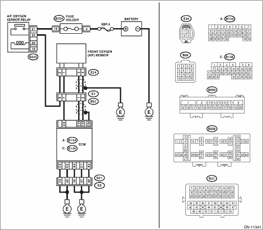
Wiring diagram:
Engine electrical system Engine Electrical System">
| STEP | CHECK | YES | NO |
1.CHECK FRONT OXYGEN (A/F) SENSOR CONNECTOR AND COUPLING CONNECTOR.
Has water entered the connector?
Completely remove any water inside.
Diagnostic Procedure with Diagnostic Trouble Code (DTC) > DTC P0131 A/F / O2 SENSOR CIRCUIT LOW VOLTAGE BANK 1 SENSOR 1">Go to Step 2.
2.CHECK HARNESS BETWEEN ECM AND FRONT OXYGEN (A/F) SENSOR CONNECTOR.
1) Turn the ignition switch to OFF.
2) Disconnect the connector from ECM.
3) Disconnect the connectors from front oxygen (A/F) sensor.
4) Measure the resistance between ECM connector and chassis ground.
Connector & terminal
(B136) No. 18 — Chassis ground:
(B136) No. 19 — Chassis ground:
Is the resistance 1 M? or more?
Diagnostic Procedure with Diagnostic Trouble Code (DTC) > DTC P0131 A/F / O2 SENSOR CIRCUIT LOW VOLTAGE BANK 1 SENSOR 1">Go to Step 3.
Repair the short circuit to ground in harness between ECM connector and front oxygen (A/F) sensor connector.
3.CHECK FOR POOR CONTACT.
Check for poor contact of the front oxygen (A/F) sensor connector.
Is there poor contact of front oxygen (A/F) sensor connector?
Repair the poor contact of front oxygen (A/F) sensor connector.
Replace the front oxygen (A/F) sensor. Front Oxygen (A/F) Sensor">
1. OUTLINE OF DIAGNOSIS
Detect the open or short circuit of sensor.
Judge as NG, when the element voltage is out of the specified range.
2. COMPONENT DESCRIPTION
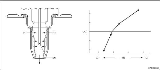
(A) | Electromotive force | (B) | Air fuel ratio | (C) | Rich |
(D) | Lean | ||||
(1) | Exhaust gas | (2) | Zirconia element oxygen |
3. EXECUTION CONDITION
Secondary Parameters | Execution condition |
Battery voltage | ≥ 10.9 V |
4. GENERAL DRIVING CYCLE
Always perform the diagnosis continuously.
5. DIAGNOSTIC METHOD
If the duration of time while the following conditions are met is longer than the time indicated, judge as NG.
Malfunction Criteria | Threshold Value |
Input voltage (+) | < 0.4 V |
or | |
Input voltage (−) | < 0.4 V |
or | |
|Input voltage (+) − Input voltage (−)| | < 0.1 V |
ECM input voltage (−) | > 3.8 V and < 4.7 V |
Time Needed for Diagnosis:
Input voltage (+): 1000 ms
Input voltage (−): 1000 ms
Malfunction Indicator Light Illumination: Illuminates as soon as a malfunction occurs.
 Dtc p0123 throttle/pedal position sensor/switch "a" circuit high
ENGINE (DIAGNOSTICS)(H4DO) > Diagnostic Procedure with Diagnostic Trouble Code (DTC)DTC P0123 THROTTLE/PEDAL POSITION SENSOR/SWITCH "A" CIRCUIT HIGHDTC detecting condition:Immediately at ...
 Dtc p0132 a/f / o2 sensor circuit high voltage bank 1 sensor 1
ENGINE (DIAGNOSTICS)(H4DO) > Diagnostic Procedure with Diagnostic Trouble Code (DTC)DTC P0132 A/F / O2 SENSOR CIRCUIT HIGH VOLTAGE BANK 1 SENSOR 1DTC DETECTING CONDITION:Immediately at fault recogn ...
Other materials:
Installation
SECURITY AND LOCKS > Keyless Access CMINSTALLATIONCAUTION:• When the control module related to immobilizer has been replaced, be sure to perform the registration of immobilizer system. For detailed operation procedure, refer to “Type D” described in “REGISTRATION MANUAL FO ...
Operation
ENTERTAINMENT > Navigation SystemOPERATION1. SUBARU STARLINK CONNECTION ID DISPLAY1. Turn the ignition switch to ACC.2. Press the AUDIO/TUNE knob (b) five times with the HOME button (a) pressed to display the {Service Menu} screen.3. Touch the {Product Information} (c) to display the {Product Inf ...
Electrical specification
KEYLESS ACCESS WITH PUSH BUTTON START SYSTEM (DIAGNOSTICS) > Control Module I/O SignalELECTRICAL SPECIFICATION1. KEYLESS ACCESS CMTerminal No.Terminal symbolContent(B572) No. 2+B+B(B572) No. 3INDSStart switch indicator (green) output(B572) No. 5N-SWNeutral switch input(B572) No. 7STSWSTSW output( ...
