Subaru Crosstrek Service Manual: Dtc p0122 throttle/pedal position sensor/switch "a" circuit low
ENGINE (DIAGNOSTICS)(H4DO) > Diagnostic Procedure with Diagnostic Trouble Code (DTC)
DTC P0122 THROTTLE/PEDAL POSITION SENSOR/SWITCH "A" CIRCUIT LOW
DTC detecting condition:
Immediately at fault recognition
Trouble symptom:
• Improper idling
• Engine stall
• Poor driving performance
CAUTION:
After servicing or replacing faulty parts, perform Clear Memory Mode Clear Memory Mode > OPERATION"> , and Inspection Mode Inspection Mode > PROCEDURE">.
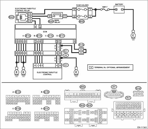
Wiring diagram:
Engine electrical system Engine Electrical System">
| STEP | CHECK | YES | NO |
1.CHECK HARNESS BETWEEN ECM AND ELECTRONIC THROTTLE CONTROL CONNECTOR.
1) Turn the ignition switch to OFF.
2) Disconnect the connector from ECM.
3) Disconnect the connectors from electronic throttle control.
4) Measure the resistance between ECM connector and chassis ground.
Connector & terminal
(B134) No. 19 — Chassis ground:
(B134) No. 18 — Chassis ground:
(B134) No. 18 — (B136) No. 4:
Is the resistance 1 M? or more?
Diagnostic Procedure with Diagnostic Trouble Code (DTC) > DTC P0122 THROTTLE/PEDAL POSITION SENSOR/SWITCH "A" CIRCUIT LOW">Go to Step 2.
Repair the ground short circuit of harness between ECM connector and electronic throttle control connector.
2.CHECK SHORT CIRCUIT INSIDE THE ECM.
1) Connect the connector to ECM.
2) Measure the resistance between electronic throttle control connector and engine ground.
Connector & terminal
(E57) No. 6 — Engine ground:
Is the resistance 1 M? or more?
Replace the electronic throttle control. Throttle Body">
Repair the ground short circuit of harness between ECM connector and electronic throttle control connector. Replace the ECM if defective. Engine Control Module (ECM)">
1. OUTLINE OF DIAGNOSIS
Detect the open or short circuit of throttle position sensor 1.
Judge as NG if out of specification.
2. COMPONENT DESCRIPTION
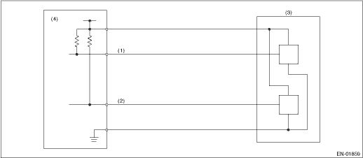
(1) | Throttle position sensor 1 signal | (3) | Throttle position sensor | (4) | Engine control module (ECM) |
(2) | Throttle position sensor 2 signal |
3. EXECUTION CONDITION
Secondary Parameters | Execution condition |
Battery voltage | ≥ 6 V |
4. GENERAL DRIVING CYCLE
Always perform the diagnosis continuously.
5. DIAGNOSTIC METHOD
If the duration of time while the following conditions are met is longer than the time indicated, judge as NG.
Malfunction Criteria | Threshold Value |
Sensor 1 input voltage | ≤ 0.267 V |
Time Needed for Diagnosis: 24 ms
Malfunction Indicator Light Illumination: Illuminates as soon as a malfunction occurs.
 Dtc p0118 engine coolant temperature sensor 1 circuit high
ENGINE (DIAGNOSTICS)(H4DO) > Diagnostic Procedure with Diagnostic Trouble Code (DTC)DTC P0118 ENGINE COOLANT TEMPERATURE SENSOR 1 CIRCUIT HIGHDTC detecting condition:Immediately at fault recognitio ...
 Dtc p0123 throttle/pedal position sensor/switch "a" circuit high
ENGINE (DIAGNOSTICS)(H4DO) > Diagnostic Procedure with Diagnostic Trouble Code (DTC)DTC P0123 THROTTLE/PEDAL POSITION SENSOR/SWITCH "A" CIRCUIT HIGHDTC detecting condition:Immediately at ...
Other materials:
Inspection
SECURITY AND LOCKS > Rear Lock ButtonINSPECTION1. Using the Subaru Select Monitor, display «Rear gate/Trunk UNLOCK output» from «Data monitor».2. Check if the display changes when the rear lock button is operated.3. If the display is not correct as the result of inspection, refer to “Ge ...
To arm the system using the keyless access function (if equipped)
1. Close all windows and the moonroof (if
equipped)
2. Turn the push-button ignition switch to
the "OFF" position.
3. Open the doors and get out of the
vehicle.
4. Make sure that the engine hood is
locked.
5. Close all doors and the rear gate.
Door lock sensor
Security i ...
Dtc b11f2 front impact deployment
AIRBAG SYSTEM (DIAGNOSTICS) > Diagnostic Chart with Trouble CodeDTC B11F2 FRONT IMPACT DEPLOYMENTDIAGNOSIS START CONDITION:Ignition voltage is 10 V to 16 V.DTC DETECTING CONDITION:This DTC is indicated when the front airbag module and the pretensioner are deployed.Once this DTC is displayed, the ...
