Subaru Crosstrek Service Manual: Dtc p0102 mass or volume air flow sensor "a" circuit low
ENGINE (DIAGNOSTICS)(H4DO) > Diagnostic Procedure with Diagnostic Trouble Code (DTC)
DTC P0102 MASS OR VOLUME AIR FLOW SENSOR "A" CIRCUIT LOW
DTC detecting condition:
Immediately at fault recognition
Trouble symptom:
• Improper idling
• Engine stall
• Poor driving performance
CAUTION:
After servicing or replacing faulty parts, perform Clear Memory Mode Clear Memory Mode > OPERATION"> , and Inspection Mode Inspection Mode > PROCEDURE">.
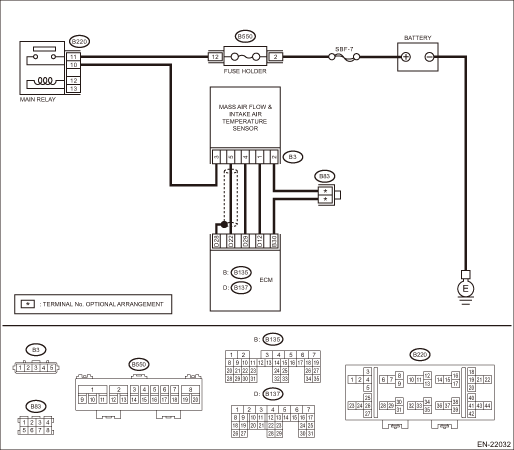
Wiring diagram:
Engine electrical system Engine Electrical System">
| STEP | CHECK | YES | NO |
1.CHECK CURRENT DATA.
1) Start the engine.
2) Read the value of «Air Flow Sensor Voltage» using Subaru Select Monitor.
NOTE:
For detailed operation procedures, refer to “Current Data Display For Engine”. Subaru Select Monitor">
Is the value of «Air Flow Sensor Voltage» less than 0.2 V?
Diagnostic Procedure with Diagnostic Trouble Code (DTC) > DTC P0102 MASS OR VOLUME AIR FLOW SENSOR "A" CIRCUIT LOW">Go to Step 2.
Even if DTC is detected, the circuit has returned to a normal condition at this time. Reproduce the failure, and then perform the diagnosis again.
NOTE:
In this case, temporary poor contact of connector, temporary open or short circuit of harness may be the cause.
2.CHECK POWER SUPPLY OF MASS AIR FLOW AND INTAKE AIR TEMPERATURE SENSOR.
1) Turn the ignition switch to OFF.
2) Disconnect the connectors from the mass air flow and intake air temperature sensor.
3) Turn the ignition switch to ON.
4) Measure the voltage between mass air flow and intake air temperature sensor connector and engine ground.
Connector & terminal
(B3) No. 3 (+) — Engine ground (−):
Is the voltage 10 V or more?
Diagnostic Procedure with Diagnostic Trouble Code (DTC) > DTC P0102 MASS OR VOLUME AIR FLOW SENSOR "A" CIRCUIT LOW">Go to Step 3.
Repair the harness and connector.
NOTE:
In this case, repair the following item:
• Open circuit in harness between main relay and mass air flow and intake air temperature sensor connector
• Poor contact of main relay connector
3.CHECK HARNESS BETWEEN ECM AND MASS AIR FLOW AND INTAKE AIR TEMPERATURE SENSOR CONNECTOR.
1) Turn the ignition switch to OFF.
2) Disconnect the connector from ECM.
3) Measure the resistance of harness between ECM connector and the mass air flow and intake air temperature sensor connector.
Connector & terminal
(B137) No. 22 — (B3) No. 5:
Is the resistance less than 1 ??
Diagnostic Procedure with Diagnostic Trouble Code (DTC) > DTC P0102 MASS OR VOLUME AIR FLOW SENSOR "A" CIRCUIT LOW">Go to Step 4.
Repair the open circuit of harness between ECM connector and the mass air flow and intake air temperature sensor connector.
4.CHECK HARNESS BETWEEN ECM AND MASS AIR FLOW AND INTAKE AIR TEMPERATURE SENSOR CONNECTOR.
Measure the resistance between ECM connector and chassis ground.
Connector & terminal
(B137) No. 22 — Chassis ground:
Is the resistance 1 M? or more?
Diagnostic Procedure with Diagnostic Trouble Code (DTC) > DTC P0102 MASS OR VOLUME AIR FLOW SENSOR "A" CIRCUIT LOW">Go to Step 5.
Repair the ground short circuit of harness between ECM connector and the mass air flow and intake air temperature sensor connector.
5.CHECK FOR POOR CONTACT.
Check for poor contact of ECM and mass air flow and intake air temperature sensor connector.
Is there poor contact of ECM or mass air flow and intake air temperature sensor connector?
Repair the poor contact of ECM or mass air flow and intake air temperature sensor connector.
Replace the mass air flow and intake air temperature sensor. Mass Air Flow and Intake Air Temperature Sensor">
1. OUTLINE OF DIAGNOSIS
Detect open or short circuits of the air flow sensor.
Judge as NG if out of specification.
2. COMPONENT DESCRIPTION
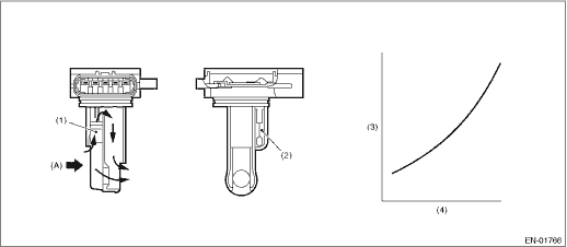
(A) | Air | ||||
(1) | Air flow sensor | (3) | Voltage (V) | (4) | Intake air amount (kg (lb)/s) |
(2) | Intake air temperature sensor |
3. EXECUTION CONDITION
Secondary Parameters | Execution condition |
None |
4. GENERAL DRIVING CYCLE
Always perform the diagnosis continuously.
5. DIAGNOSTIC METHOD
If the duration of time while the following conditions are met is longer than the time indicated, judge as NG.
Malfunction Criteria | Threshold Value |
Output voltage | ≤ 0.127 V |
Time Needed for Diagnosis: 500 ms
Malfunction Indicator Light Illumination: Illuminates as soon as a malfunction occurs.
 Dtc p0101 mass or volume air flow sensor "a" circuit range/performance
ENGINE (DIAGNOSTICS)(H4DO) > Diagnostic Procedure with Diagnostic Trouble Code (DTC)DTC P0101 MASS OR VOLUME AIR FLOW SENSOR "A" CIRCUIT RANGE/PERFORMANCEDTC DETECTING CONDITION:Detected ...
 Dtc p0103 mass or volume air flow sensor "a" circuit high
ENGINE (DIAGNOSTICS)(H4DO) > Diagnostic Procedure with Diagnostic Trouble Code (DTC)DTC P0103 MASS OR VOLUME AIR FLOW SENSOR "A" CIRCUIT HIGHDTC detecting condition:Immediately at fault r ...
Other materials:
Shift lock function
The shift lock function helps prevent the
improper operation of the select lever.
The select lever cannot be operated
unless the ignition switch is turned to the
"ON" position and the brake pedal is
depressed.
The select lever cannot be moved from
the "P" position to any other positio ...
Removal
EXTERIOR/INTERIOR TRIM > Cowl PanelREMOVAL1. Open the front hood.2. Remove the arm assembly - windshield wiper. Front Wiper Arm > REMOVAL">3. Remove the cowl panel - side.(1) Remove the clips.(2) Release the claws, and then remove the cowl panel - side.CAUTION:Pulling with excessive f ...
Component
REAR SUSPENSION > General DescriptionCOMPONENT1. REAR SUSPENSION(1)Rear sub frame ASSY(11)Stopper LWRTightening torque: N·m (kgf-m, ft-lb)(2)Stopper UPR(12)Flange nutT1:30 (3.06, 22.1)(3)Stay - rear frame COMPL(13)Rear stabilizerT2:33 (3.36, 24.3)(4)Front sub frame support(14)Bushing - sta ...
