Subaru Crosstrek Service Manual: Dtc p0037 a/f / o2 heater control circuit low bank 1 sensor 2
ENGINE (DIAGNOSTICS)(H4DO) > Diagnostic Procedure with Diagnostic Trouble Code (DTC)
DTC P0037 A/F / O2 HEATER CONTROL CIRCUIT LOW BANK 1 SENSOR 2
DTC DETECTING CONDITION:
Detected when two consecutive driving cycles with fault occur.
CAUTION:
After servicing or replacing faulty parts, perform Clear Memory Mode Clear Memory Mode > OPERATION"> , and Inspection Mode Inspection Mode > PROCEDURE">.
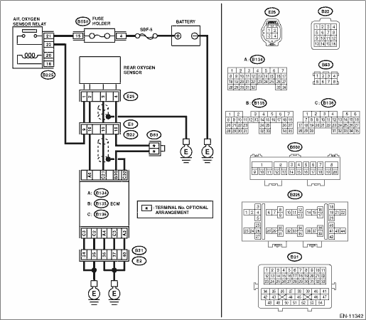
WIRING DIAGRAM:
Engine electrical system Engine Electrical System">
| STEP | CHECK | YES | NO |
1.CHECK POWER SUPPLY TO REAR OXYGEN SENSOR.
1) Turn the ignition switch to OFF.
2) Disconnect the connector from rear oxygen sensor.
3) Turn the ignition switch to ON.
4) Measure the voltage between rear oxygen sensor connector and engine ground.
Connector & terminal
(E25) No. 1 (+) — Engine ground (−):
Is the voltage 10 V or more?
Diagnostic Procedure with Diagnostic Trouble Code (DTC) > DTC P0037 A/F / O2 HEATER CONTROL CIRCUIT LOW BANK 1 SENSOR 2">Go to Step 2.
Repair the power supply line. Or replace the main relay.
NOTE:
In this case, repair the following item:
• Open circuit in harness between A/F, oxygen sensor relay connector and rear oxygen sensor connector
• Poor contact of A/F, oxygen sensor relay connector
• Poor contact of coupling connector
• Malfunction of A/F, oxygen sensor relay
2.CHECK HARNESS BETWEEN ECM AND REAR OXYGEN SENSOR CONNECTOR.
1) Turn the ignition switch to OFF.
2) Disconnect the connector from ECM.
3) Measure the resistance between ECM connector and oxygen sensor connector.
Connector & terminal
(B134) No. 6 — (E25) No. 2:
Is the resistance less than 1 ??
Diagnostic Procedure with Diagnostic Trouble Code (DTC) > DTC P0037 A/F / O2 HEATER CONTROL CIRCUIT LOW BANK 1 SENSOR 2">Go to Step 3.
Repair the harness and connector.
NOTE:
In this case, repair the following item:
• Open circuit in harness between ECM connector and rear oxygen sensor connector
• Poor contact of coupling connector
3.CHECK GROUND CIRCUIT FOR ECM.
Measure the resistance of harness between ECM connector and chassis ground.
Connector & terminal
(B134) No. 3 — Chassis ground:
(B134) No. 4 — Chassis ground:
(B136) No. 1 — Chassis ground:
(B136) No. 2 — Chassis ground:
(B136) No. 3 — Chassis ground:
Is the resistance less than 5 ??
Diagnostic Procedure with Diagnostic Trouble Code (DTC) > DTC P0037 A/F / O2 HEATER CONTROL CIRCUIT LOW BANK 1 SENSOR 2">Go to Step 4.
Repair the harness and connector.
NOTE:
In this case, repair the following item:
• Open circuit of harness between ECM connector and engine ground
• Poor contact of coupling connector
4.CHECK REAR OXYGEN SENSOR.
Measure the resistance between rear oxygen sensor terminals.
Terminals
No. 2 — No. 1:
Is the resistance 5 — 6.4 ??
Repair the poor contact of ECM connector.
Replace the rear oxygen sensor. Rear Oxygen Sensor">
1. OUTLINE OF DIAGNOSIS
Detect the rear oxygen sensor heater open or short circuit.
The rear oxygen sensor heater performs duty control, and the output terminal voltage at ON is 0 V, and the output terminal voltage at OFF is the battery voltage.
Judge as NG when the terminal voltage remains Low.
2. COMPONENT DESCRIPTION
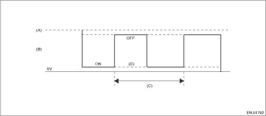
(A) | Battery voltage | (B) | Output voltage of the rear oxygen sensor heater | (C) | 256 ms (cycles) |
(D) | Low error |
3. EXECUTION CONDITION
Secondary Parameters | Execution condition |
Battery voltage | ≥ 10.9 V |
Secondary oxygen sensor heater control duty | < 75 % |
4. GENERAL DRIVING CYCLE
After starting the engine, perform the diagnosis continuously when engine is low speed.
5. DIAGNOSTIC METHOD
If the duration of time while the following conditions are met is longer than the time indicated, judge as NG.
Malfunction Criteria | Threshold Value |
Measured secondary oxygen sensor heater control voltage | < 12 V battery system voltage ? 0.20 V |
Time Needed for Diagnosis: 8 ms ? 1250 time(s)
Malfunction Indicator Light Illumination: Illuminates when malfunction occurs in 2 continuous driving cycles.
 Dtc p0032 a/f / o2 heater control circuit high bank 1 sensor 1
ENGINE (DIAGNOSTICS)(H4DO) > Diagnostic Procedure with Diagnostic Trouble Code (DTC)DTC P0032 A/F / O2 HEATER CONTROL CIRCUIT HIGH BANK 1 SENSOR 1DTC DETECTING CONDITION:Immediately at fault recogn ...
 Dtc p0038 a/f / o2 heater control circuit high bank 1 sensor 2
ENGINE (DIAGNOSTICS)(H4DO) > Diagnostic Procedure with Diagnostic Trouble Code (DTC)DTC P0038 A/F / O2 HEATER CONTROL CIRCUIT HIGH BANK 1 SENSOR 2DTC DETECTING CONDITION:Detected when two consecuti ...
Other materials:
Fuel gauge
Fuel gauge (type A)
Trip knob
Fuel gauge (type B)
Trip knob (U.S.-spec. models)
Trip knob (except U.S.-spec. models)
The fuel gauge is displayed when the
ignition is in the "ON" position, and it
shows the approximate amount of fuel
remaining in the tank.
The gauge indic ...
Removal
LIGHTING SYSTEM > Front Fog Light AssemblyREMOVAL1. Disconnect the ground cable from battery. NOTE">2. Lift up the vehicle.3. Remove the screw and clips, and turn over the front side of the mud guard - front.4. From the bottom of the bumper face - front, remove the fog light assembly - f ...
Power window operation by passengers
Passenger's side power window switches
Each passenger window can be controlled
by the power window switch located on
the door.
Operating the windows
To open:
Press the switch down and hold it until the
window reaches the desired position.
To close:
Pull the switch up and hold it u ...
