Subaru Crosstrek Service Manual: Dtc c1511 valve relay
VEHICLE DYNAMICS CONTROL (VDC) (DIAGNOSTICS) > Diagnostic Procedure with Diagnostic Trouble Code (DTC)
DTC C1511 VALVE RELAY
DTC detecting condition:
Defective valve relay
Trouble symptom:
• ABS does not operate.
• EBD does not operate.
• VDC does not operate.
• Hill start assist does not operate.
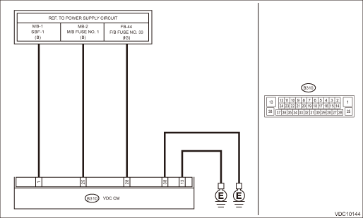
Wiring diagram:
Vehicle dynamics control system Vehicle Dynamics Control System > WIRING DIAGRAM">
| STEP | CHECK | YES | NO |
1.CHECK VDCCM&H/U INPUT VOLTAGE.
1) Turn the ignition switch to OFF.
2) Disconnect the connector from the VDCCM&H/U.
3) Run the engine at idle.
4) Measure the voltage between VDCCM&H/U connector and chassis ground.
Connector & terminal
(B310) No. 25 (+) — Chassis ground (−):
(B310) No. 28 (+) — Chassis ground (−):
Is the voltage 10 — 15 V?
Diagnostic Procedure with Diagnostic Trouble Code (DTC) > DTC C1511 VALVE RELAY">Go to Step 2.
Repair the power supply circuit.
2.CHECK VDCCM&H/U INPUT VOLTAGE.
Calculate the voltage difference measured in step 1.
A: (B310) No. 25 (+) — Chassis ground (−):
B: (B310) No. 28 (+) — Chassis ground (−):
Is the voltage difference between A and B 2 V or more?
Repair the power supply circuit.
Diagnostic Procedure with Diagnostic Trouble Code (DTC) > DTC C1511 VALVE RELAY">Go to Step 3.
3.CHECK VDCCM&H/U GROUND CIRCUIT (CHECK FOR OPEN CIRCUIT).
1) Turn the ignition switch to OFF.
2) Measure the resistance between VDCCM&H/U connector and chassis ground.
Connector & terminal
(B310) No. 38 — Chassis ground:
Is the resistance less than 10 ??
Diagnostic Procedure with Diagnostic Trouble Code (DTC) > DTC C1511 VALVE RELAY">Go to Step 4.
Repair the VDCCM&H/U ground harness.
4.CHECK POOR CONTACT OF CONNECTORS.
Is there poor contact of connector between generator, battery and VDCCM&H/U?
Repair the connector.
Diagnostic Procedure with Diagnostic Trouble Code (DTC) > DTC C1511 VALVE RELAY">Go to Step 5.
5.CHECK VDCCM&H/U.
1) Connect all connectors.
2) Perform the Clear Memory Mode. Clear Memory Mode">
3) Perform the Inspection Mode. Inspection Mode">
4) Read the DTC. Read Diagnostic Trouble Code (DTC)">
Is the same DTC displayed?
Replace the VDCCM only. VDC Control Module and Hydraulic Control Unit (VDCCM&H/U) > REPLACEMENT">
Diagnostic Procedure with Diagnostic Trouble Code (DTC) > DTC C1511 VALVE RELAY">Go to Step 6.
6.CHECK DETECTION OF OTHER DTCS FOR VDC.
Read Diagnostic Trouble Code (DTC)">
Is any other DTC displayed?
Perform the diagnosis according to DTC. List of Diagnostic Trouble Code (DTC)">
Currently, it is normal. There may have been a temporary poor contact in the harness and connector or a temporary noise interference.
 Dtc c0075 wheel cylinder pressure sensor output
VEHICLE DYNAMICS CONTROL (VDC) (DIAGNOSTICS) > Diagnostic Procedure with Diagnostic Trouble Code (DTC)DTC C0075 WHEEL CYLINDER PRESSURE SENSOR OUTPUTDTC detecting condition:Defective pressure senso ...
 Dtc c1512 valve system
VEHICLE DYNAMICS CONTROL (VDC) (DIAGNOSTICS) > Diagnostic Procedure with Diagnostic Trouble Code (DTC)DTC C1512 VALVE SYSTEMNOTE:For the diagnostic procedure, refer to “DTC C1362 NORMAL CLOSI ...
Other materials:
Removal
STARTING/CHARGING SYSTEMS(H4DO) > GeneratorREMOVAL1. Remove the V-belt covers.2. Disconnect the ground cable from battery. NOTE">3. Remove the V-belts. V-belt > REMOVAL">4. Disconnect the connector (A) and terminal (B) from the generator, and remove the clip (C).5. Remove the ...
Keyless access setting (models with "keyless access with pushbutton start
system")
Preparation for keyless access settings
1. Perform the preparation steps according
to "Preparation for car settings"
2. Operate the " " or "
" switch to
select the "Keyless Access Setting" item.
Then push the button.
Driver's door unlock setting
1. Perform the preparatio ...
Installation
AIRBAG SYSTEM > Satellite Safing SensorINSTALLATIONCAUTION:• Do not reuse the bolt and nut.Always replace with the specified new bolts and nuts.• When installing the cover - satellite safing, push the cover securely until it contacts the floor panel.• If the cover - satellite sa ...
