Subaru Crosstrek Service Manual: Dtc b2271 ign relay control circuit
KEYLESS ACCESS WITH PUSH BUTTON START SYSTEM (DIAGNOSTICS) > Diagnostic Procedure with Diagnostic Trouble Code (DTC)
DTC B2271 IGN RELAY CONTROL CIRCUIT
DTC detecting condition:
• When malfunction is detected in IG1 and IG2 drive circuits in the keyless access CM.
• When malfunction is detected in IG hold circuit in the keyless access CM.
Trouble symptom:
Not all functions operate at IGN ON.
CAUTION:
For replacement procedure of keyless access CM, refer to the “REGISTRATION MANUAL FOR IMMOBILIZER” provided as a separate volume.
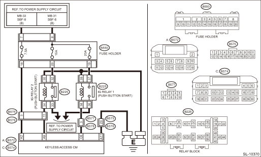
Wiring diagram:
Push button start system Push Button Start System > WIRING DIAGRAM">
| STEP | CHECK | YES | NO |
1.CHECK LAN SYSTEM.
Inspect LAN system. Basic Diagnostic Procedure > PROCEDURE">
Is LAN system normal?
Diagnostic Procedure with Diagnostic Trouble Code (DTC) > DTC B2271 IGN RELAY CONTROL CIRCUIT">Go to Step 2.
Perform the inspection according to the diagnosis for LAN system.
2.CHECK FUSE.
Check the fuse. Relay and Fuse">
Is the fuse OK?
Diagnostic Procedure with Diagnostic Trouble Code (DTC) > DTC B2271 IGN RELAY CONTROL CIRCUIT">Go to Step 3.
Replace the fuse. When the replaced fuse is blown immediately, check the power supply circuit for short-circuited.
3.CHECK HARNESS.
1) Disconnect the keyless access CM connector.
2) Using a tester, measure the voltage between the keyless access CM connector and chassis ground.
Connector & terminal
(B572) No. 2 (+) — Chassis ground (−):
Is the voltage 9.5 — 16 V?
Diagnostic Procedure with Diagnostic Trouble Code (DTC) > DTC B2271 IGN RELAY CONTROL CIRCUIT">Go to Step 4.
Check the power supply circuit.
4.CHECK HARNESS.
Using a tester, measure the resistance between the keyless access CM connector and chassis ground.
Connector & terminal
(B572) No. 11 — Chassis ground:
Is the resistance less than 1 ??
Diagnostic Procedure with Diagnostic Trouble Code (DTC) > DTC B2271 IGN RELAY CONTROL CIRCUIT">Go to Step 5.
Repair or replace the open circuit of harness.
5.CHECK HARNESS.
1) Disconnect the keyless access CM connector.
2) Using a tester, measure the resistance between the keyless access CM connector and chassis ground.
Connector & terminal
(B572) No. 9 — Chassis ground:
Is resistance 74.15 — 460.88 ?? (20°C)
Diagnostic Procedure with Diagnostic Trouble Code (DTC) > DTC B2271 IGN RELAY CONTROL CIRCUIT">Go to Step 6.
Check IG relay 2. Diagnostic Procedure with Diagnostic Trouble Code (DTC) > DTC B2271 IGN RELAY CONTROL CIRCUIT">Go to Step 7.
6.CHECK HARNESS.
1) Disconnect the keyless access CM connector.
2) Using a tester, measure the resistance between the keyless access CM connector and chassis ground.
Connector & terminal
(B574) No. 6 — Chassis ground:
Is resistance 50.87 — 72.17 ?? (20°C)
Diagnostic Procedure with Diagnostic Trouble Code (DTC) > DTC B2271 IGN RELAY CONTROL CIRCUIT">Go to Step 8.
Check IG relay 1. Diagnostic Procedure with Diagnostic Trouble Code (DTC) > DTC B2271 IGN RELAY CONTROL CIRCUIT">Go to Step 7.
7.CHECK RELAY.
Perform unit inspection of IG relay 1 and IG relay 2. Relay and Fuse > INSPECTION">
Is the relay OK?
Diagnostic Procedure with Diagnostic Trouble Code (DTC) > DTC B2271 IGN RELAY CONTROL CIRCUIT">Go to Step 8.
Replace the relay. IG Relay1 (Push Button Start) > REMOVAL"> IG Relay2 (Push Button Start) > REMOVAL">
8.CHECK KEYLESS ACCESS CM.
1) Connect the keyless access CM connector.
2) Using a tester, measure the voltage between the terminals of keyless access CM connector.
Connector & terminal
(B574) No. 6 (+) — Chassis ground (−):
(B572) No. 9 (+) — Chassis ground (−):
Is the voltage 1 V or less > 9.5 — 16 V when ACC > IGN ON?
Even if DTC is displayed, the circuit has returned to a normal condition at this time. Reproduce the failure, and then perform the diagnosis again.
NOTE:
In this case, temporary poor contact of connector, temporary open or short circuit of harness may be the cause.
Replace the keyless access CM. Keyless Access CM > REMOVAL">
 Dtc b1242 wireless tuner
KEYLESS ACCESS WITH PUSH BUTTON START SYSTEM (DIAGNOSTICS) > Diagnostic Procedure with Diagnostic Trouble Code (DTC)DTC B1242 WIRELESS TUNERDTC detecting condition:When short circuit occurs in harn ...
 Dtc b2274 acc relay control circuit
KEYLESS ACCESS WITH PUSH BUTTON START SYSTEM (DIAGNOSTICS) > Diagnostic Procedure with Diagnostic Trouble Code (DTC)DTC B2274 ACC RELAY CONTROL CIRCUITDTC detecting condition:When malfunction is de ...
Other materials:
Removal
FUEL INJECTION (FUEL SYSTEMS)(H4DO) > Mass Air Flow and Intake Air Temperature SensorREMOVAL1. Disconnect the ground cable from battery.2. Disconnect the connector (A) from the mass air flow and intake air temperature sensor, and remove the mass air flow and intake air temperature sensor. ...
Seatbelt maintenance
To clean the seatbelts, use a mild soap
and lukewarm water. Never bleach or dye
the belts because this could seriously
affect their strength.
Inspect the seatbelts and attachments
including the webbing and all hardware
periodically for cracks, cuts, gashes,
tears, damage, loose bolts or wor ...
Wiring diagram
LUBRICATION(H4DO) > Oil Level SwitchWIRING DIAGRAM• Engine electrical system Engine Electrical System > WIRING DIAGRAM">• CAN communication system CAN Communication System > WIRING DIAGRAM"> ...
