Subaru Crosstrek Service Manual: Dtc b1806 open in passenger s airbag
AIRBAG SYSTEM (DIAGNOSTICS) > Diagnostic Chart with Trouble Code
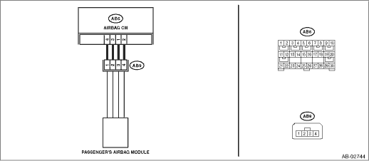
DTC B1806 OPEN IN PASSENGER’S AIRBAG
Diagnosis start condition:
Ignition voltage is 10 V to 16 V.
DTC detecting condition:
• Airbag main harness circuit is open.
• Airbag module harness (passenger’s side) circuit is open.
• Passenger’s airbag module is faulty.
• Airbag control module is faulty.
CAUTION:
Before performing diagnosis, refer to “CAUTION” in “General Description”. General Description > CAUTION">
Wiring diagram:
Airbag system Airbag System > WIRING DIAGRAM">
| STEP | CHECK | YES | NO |
1.CHECK POOR CONTACT OF CONNECTORS.
Check for poor contact of the connectors between the airbag control module and the passenger’s airbag module.
Is there poor contact?
Replace the airbag harness.
Diagnostic Chart with Trouble Code > DTC B1806 OPEN IN PASSENGER’S AIRBAG">Go to Step 2.
2.CHECK AIRBAG MAIN HARNESS (PASSENGER’S AIRBAG HARNESS).
1) Turn the ignition switch to OFF, disconnect the battery ground cable, and wait for 60 seconds or more.
2) Disconnect the connectors (AB7) and (AB2).
3) Disconnect the connector (AB66) from the driver’s knee airbag module.
4) Disconnect the connectors (AB6, AB17, AB18) from airbag control module.
5) Disconnect the passenger’s airbag module connector (AB9).
6) Using a probe, measure the resistance between the terminals of connector (AB9). General Description > PREPARATION TOOL">
CAUTION:
When measuring the resistance, make sure that the probe is inserted from the back side (harness side) of the connector. Also, do not insert the probe forcibly.
Connector & terminal
(AB9) No. 1 — (AB9) No. 2:
Is the resistance less than 10 ??
Diagnostic Chart with Trouble Code > DTC B1806 OPEN IN PASSENGER’S AIRBAG">Go to Step 3.
Replace the airbag main harness along with body harness.
3.CHECK AIRBAG CONTROL MODULE.
1) Connect the connectors (AB6, AB17, AB18) and the airbag control module.
2) Connect the connectors (AB7) and (AB2).
3) Connect the connector (AB66) to the driver’s knee airbag module.
4) Using a probe, short the terminals No. 1 and No. 2 of connector (AB9). General Description > PREPARATION TOOL">
CAUTION:
When shorting the terminals, make sure that the probe is inserted from the back side (harness side) of the connector. Also, do not insert the probe forcibly.
Connector & terminal
(AB9) No. 1 — (AB9) No. 2:
5) Connect the battery ground terminal and turn the ignition switch to ON.
6) Perform the Inspection Mode. Inspection Mode">
7) Read the DTC. (Current malfunction) Read Diagnostic Trouble Code (DTC)">
Is DTC B1806 displayed?
Replace the airbag control module. Airbag Control Module > REMOVAL">
Diagnostic Chart with Trouble Code > DTC B1806 OPEN IN PASSENGER’S AIRBAG">Go to Step 4.
4.CHECK PASSENGER’S AIRBAG MODULE.
1) Turn the ignition switch to OFF, disconnect the battery ground cable, and wait for 60 seconds or more.
2) Connect the passenger’s airbag module connector (AB9).
3) Connect the battery negative terminal, and clear the memory. Clear Memory Mode">
4) Perform the Inspection Mode. Inspection Mode">
5) Read the DTC. (Current malfunction) Read Diagnostic Trouble Code (DTC)">
Is DTC B1806 displayed?
Replace the passenger’s airbag module. Passenger’s Airbag Module > REMOVAL">
Diagnostic Chart with Trouble Code > DTC B1806 OPEN IN PASSENGER’S AIRBAG">Go to Step 5.
5.CHECK FOR ANY OTHER DTC ON DISPLAY.
Is any other DTC displayed?
Check DTC using “List of Diagnostic Trouble Code (DTC)”. List of Diagnostic Trouble Code (DTC)">
Finish the diagnosis.
 Dtc b1805 short in passenger s airbag
AIRBAG SYSTEM (DIAGNOSTICS) > Diagnostic Chart with Trouble CodeDTC B1805 SHORT IN PASSENGER’S AIRBAGDiagnosis start condition:Ignition voltage is 10 V to 16 V.DTC detecting condition:• ...
 Dtc b1807 short in passenger s airbag (to ground)
AIRBAG SYSTEM (DIAGNOSTICS) > Diagnostic Chart with Trouble CodeDTC B1807 SHORT IN PASSENGER’S AIRBAG (TO GROUND)Diagnosis start condition:Ignition voltage is 10 V to 16 V.DTC detecting condi ...
Other materials:
Entering letters and numbers/list screen operation
Entering letters and numbers
When entering the Bluetooth device name
or PIN-code, or the phone number, letters
and numbers can be entered via the
screen.
Enter letters (example: In-Car-Device
setting)
Enter the desired characters (alphabet
key mode).
Switch to the screen for charac ...
Dtc b1015 key interlock circuit
BODY CONTROL SYSTEM (DIAGNOSTICS) > Diagnostic Procedure with Diagnostic Trouble Code (DTC)DTC B1015 KEY INTERLOCK CIRCUITDTC detecting condition:Ground short of key interlock circuitTrouble symptom:Key interlock does not keep lock condition.Wiring diagram:Shift lock control system Shift Lock Co ...
Disassembly
DRIVE SHAFT SYSTEM > Rear AxleDISASSEMBLY1. BUSHING - REAR AXLE HOUSINGDo not remove the bushing - rear axle housing from the rear axle housing, because it cannot be replaced. If removed, replace the rear axle housing.2. REAR BUSHING1. Remove the rear axle housing. Rear Axle > REMOVAL"&g ...
