Subaru Crosstrek Service Manual: Dtc b1014 acc power
BODY CONTROL SYSTEM (DIAGNOSTICS) > Diagnostic Procedure with Diagnostic Trouble Code (DTC)
DTC B1014 ACC POWER
DTC detecting condition:
Voltage failure caused by poor contact of ACC power supply circuit
Trouble symptom:
DRL may not illuminate.
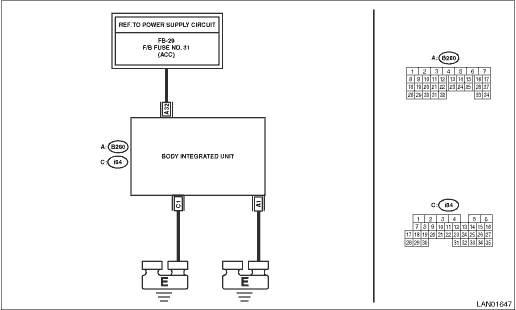
Wiring diagram:
Shift lock control system Shift Lock Control System > WIRING DIAGRAM">
| STEP | CHECK | YES | NO |
1.CHECK DTC.
Read the DTC of body integrated unit using Subaru Select Monitor. Read Diagnostic Trouble Code (DTC)">
Is B1014 current malfunction?
Diagnostic Procedure with Diagnostic Trouble Code (DTC) > DTC B1014 ACC POWER">Go to Step 2.
Diagnostic Procedure with Diagnostic Trouble Code (DTC) > DTC B1014 ACC POWER">Go to Step 5.
2.CHECK DTC.
1) Turn the ignition switch to OFF.
2) Disconnect and then connect the body integrated unit connector.
3) Wait approx. 2 minutes.
4) Turn the ignition switch to ON.
5) Read the DTC of body integrated unit using Subaru Select Monitor. Read Diagnostic Trouble Code (DTC)">
Is B1014 current malfunction?
Diagnostic Procedure with Diagnostic Trouble Code (DTC) > DTC B1014 ACC POWER">Go to Step 3.
Diagnostic Procedure with Diagnostic Trouble Code (DTC) > DTC B1014 ACC POWER">Go to Step 5.
3.CHECK FUSE.
1) Turn the ignition switch to OFF.
2) Check the fuse.
Is the fuse OK?
Diagnostic Procedure with Diagnostic Trouble Code (DTC) > DTC B1014 ACC POWER">Go to Step 4.
Replace the defective fuse.
4.CHECK HARNESS.
1) Disconnect the body integrated unit connector.
2) Using the tester, measure the voltage between terminals.
Connector & terminal
(B280) No. 32 (+) — Chassis ground (−):
Is the voltage 8.5 — 16.5 V?
Replace the body integrated unit. Body Integrated Unit">
Repair the harness between body integrated unit and fuse.
5.CHECK CONNECTOR.
1) Turn the ignition switch to OFF.
2) Disconnect the body integrated unit connector.
Is there poor contact of connector?
Repair or replace the poor contact of connector.
Even if DTC is displayed, the circuit has returned to a normal condition at this time. Reproduce the failure, and then perform the diagnosis again.
NOTE:
In this case, temporary poor contact of connector, temporary open or short circuit of harness may be the cause.
 Dtc b1013 ignition power
BODY CONTROL SYSTEM (DIAGNOSTICS) > Diagnostic Procedure with Diagnostic Trouble Code (DTC)DTC B1013 IGNITION POWERDTC detecting condition:Voltage failure caused by poor contact of IGN power supply ...
 Dtc b1015 key interlock circuit
BODY CONTROL SYSTEM (DIAGNOSTICS) > Diagnostic Procedure with Diagnostic Trouble Code (DTC)DTC B1015 KEY INTERLOCK CIRCUITDTC detecting condition:Ground short of key interlock circuitTrouble sympto ...
Other materials:
List
TELEMATICS SYSTEM (DIAGNOSTICS) > Diagnostic Code(s) DisplayLISTDTCItemNoteU0073CONTROL MODULE COMMUNICATION BUS OFF Diagnostic Procedure with Diagnostic Trouble Code (DTC) > DTC U0073 CONTROL MODULE COMMUNICATION BUS OFF">U0100LOST COMMUNICATION WITH ECM/PCM “A” Diagnostic ...
Assembly
DRIVE SHAFT SYSTEM > Rear Drive ShaftASSEMBLYCAUTION:Wrap shaft splines with vinyl tape to protect the boot from scratches.NOTE:Use specified grease.Grease:BJ, EBJ side: NKG814DOJ side: NKG8141. Install the inner race to the shaft.(1) Install the boot (BJ) or boot (EBJ) in the specified position, ...
Dtc p0353 ignition coil "c" primary control circuit/open
ENGINE (DIAGNOSTICS)(H4DO) > Diagnostic Procedure with Diagnostic Trouble Code (DTC)DTC P0353 IGNITION COIL "C" PRIMARY CONTROL CIRCUIT/OPENNOTE:For the diagnostic procedure, refer to DTC P0351. Diagnostic Procedure with Diagnostic Trouble Code (DTC) > DTC P0351 IGNITION COIL " ...
