Subaru Crosstrek Service Manual: Dtc b1011 battery control power supply
BODY CONTROL SYSTEM (DIAGNOSTICS) > Diagnostic Procedure with Diagnostic Trouble Code (DTC)
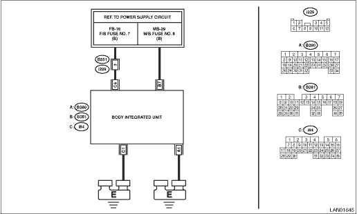
DTC B1011 BATTERY CONTROL POWER SUPPLY
DTC detecting condition:
• Voltage failure caused by poor contact of battery power supply control circuit
• Battery voltage of body integrated unit is not within the range of 8.5 — 16.5 V.
Trouble symptom:
Functions of body integrated unit stop.
NOTE:
When DTC B1012 BATTERY BACKUP POWER SUPPLY is output at the same time, all the function of body integrated unit may not operate.
Wiring diagram:
Immobilizer system Immobilizer System > WIRING DIAGRAM">
| STEP | CHECK | YES | NO |
1.CHECK DTC.
Read the DTC of body integrated unit using Subaru Select Monitor. Read Diagnostic Trouble Code (DTC)">
Is B1011 current malfunction?
Diagnostic Procedure with Diagnostic Trouble Code (DTC) > DTC B1011 BATTERY CONTROL POWER SUPPLY">Go to Step 2.
Diagnostic Procedure with Diagnostic Trouble Code (DTC) > DTC B1011 BATTERY CONTROL POWER SUPPLY">Go to Step 5.
2.CHECK DTC.
1) Turn the ignition switch to OFF.
2) Disconnect and then connect the body integrated unit connector.
3) Wait approx. 2 minutes.
4) Turn the ignition switch to ON.
5) Read the DTC of body integrated unit using Subaru Select Monitor. Read Diagnostic Trouble Code (DTC)">
Is B1011 current malfunction?
Diagnostic Procedure with Diagnostic Trouble Code (DTC) > DTC B1011 BATTERY CONTROL POWER SUPPLY">Go to Step 3.
Diagnostic Procedure with Diagnostic Trouble Code (DTC) > DTC B1011 BATTERY CONTROL POWER SUPPLY">Go to Step 5.
3.CHECK FUSE.
1) Turn the ignition switch to OFF.
2) Check the fuse.
Is the fuse OK?
Diagnostic Procedure with Diagnostic Trouble Code (DTC) > DTC B1011 BATTERY CONTROL POWER SUPPLY">Go to Step 4.
Replace the defective fuse.
4.CHECK HARNESS.
1) Disconnect the body integrated unit connector.
2) Using the tester, measure the voltage between terminals.
Connector & terminal
(i84) No. 6 (+) — Chassis ground (−):
Is the voltage 8.5 — 16.5 V?
Replace the body integrated unit. Body Integrated Unit">
Repair the harness between body integrated unit and fuse.
5.CHECK CONNECTOR.
1) Turn the ignition switch to OFF.
2) Disconnect the body integrated unit connector.
Is there poor contact of connector?
Repair or replace the poor contact of connector.
Even if DTC is displayed, the circuit has returned to a normal condition at this time. Reproduce the failure, and then perform the diagnosis again.
NOTE:
In this case, temporary poor contact of connector, temporary open or short circuit of harness may be the cause.
 Dtc b1010 body control system (biu) malfunction
BODY CONTROL SYSTEM (DIAGNOSTICS) > Diagnostic Procedure with Diagnostic Trouble Code (DTC)DTC B1010 BODY CONTROL SYSTEM (BIU) MALFUNCTIONDTC DETECTING CONDITION:System error in body integrated uni ...
 Dtc b1012 battery backup power supply
BODY CONTROL SYSTEM (DIAGNOSTICS) > Diagnostic Procedure with Diagnostic Trouble Code (DTC)DTC B1012 BATTERY BACKUP POWER SUPPLYDTC detecting condition:Voltage failure caused by poor contact of bat ...
Other materials:
Rear seats
WARNING
Seatbelts provide maximum restraint
when the occupant sits well
back and upright in the seat. Do not
put cushions or any other materials
between occupants and seatbacks
or seat cushions. If you do so, the
risk of sliding under the lap belt and
of the lap belt sliding up over the
...
Seatbelt maintenance
To clean the seatbelts, use a mild soap
and lukewarm water. Never bleach or dye
the belts because this could seriously
affect their strength.
Inspect the seatbelts and attachments
including the webbing and all hardware
periodically for cracks, cuts, gashes,
tears, damage, loose bolts or wor ...
Dtc u1651 lost communication with meter (uart)
INSTRUMENTATION/DRIVER INFO (DIAGNOSTICS) > Diagnostic Procedure with Diagnostic Trouble Code (DTC)DTC U1651 LOST COMMUNICATION WITH METER (UART)DTC detecting condition:UART data from combination meter is not received.Trouble symptom:LCD is not displayed.Wiring diagram:Multi-function display (MFD ...
