Subaru Crosstrek Service Manual: Disassembly
MANUAL TRANSMISSION AND DIFFERENTIAL(5MT) > Drive Pinion Shaft Assembly
DISASSEMBLY
NOTE:
Attach a cloth to the end of driven shaft (on the frictional side of the thrust needle bearing) to prevent damage during disassembly or reassembly.
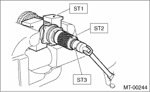
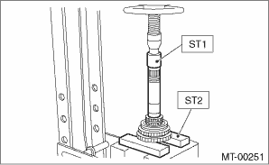
1. Flatten the tab of the lock nut. Remove the lock nut with ST1, ST2 and ST3.
| ST1 899884100 | HOLDER |
| ST2 498427100 | STOPPER |
| ST3 899988608 | SOCKET WRENCH (27) |
2. Remove the lock washer, washer, differential bevel gear sleeve, adjusting washers No. 1, No. 2 and thrust bearing.
3. Pull out the drive pinion shaft, and remove the needle bearing and drive pinion collar from driven shaft.
4. Remove the needle bearing and thrust bearing from drive pinion shaft.
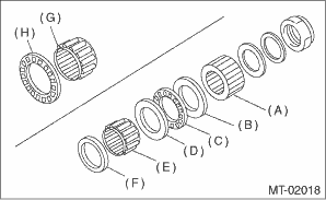
(A) | Differential bevel gear sleeve |
(B) | Adjusting washer No. 1 (25 ? 37.5 ? t) |
(C) | Thrust bearing (25 ? 37.5 ? 3) |
(D) | Adjusting washer No. 2 (25 ? 37.5 ? t) |
(E) | Needle bearing (25 ? 30 ? 20) |
(F) | Drive pinion collar |
(G) | Needle bearing (30 ? 37 ? 23) |
(H) | Thrust bearing (33 ? 50 ? 3) |
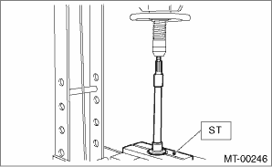
5. Remove the roller bearing and washer using ST and a press.
| ST 498077000 | REMOVER |
6. Flatten the tab of the lock nut. Remove the lock nut and lock washer using ST1 and ST2.
| ST1 499987300 | SOCKET WRENCH (50) |
| ST2 899884100 | HOLDER |
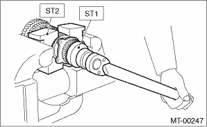
7. Remove the 5th driven gear using ST.
| ST 499857000 | 5TH DRIVEN GEAR REMOVER |
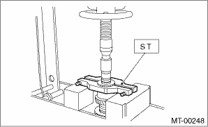
8. Remove the woodruff key.
9. Remove the double taper roller bearing and 3rd-4th driven gear using ST1 and ST2.
| ST1 499757002 | INSTALLER |
| ST2 899714110 | REMOVER |
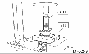
10. Remove the key.
11. Remove the 2nd driven gear, inner baulk ring, synchro cone and outer baulk ring.
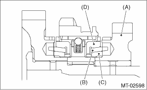
(A) | 2nd driven gear |
(B) | Synchro cone |
(C) | Inner baulk ring |
(D) | Outer baulk ring |
12. Remove the 1st driven gear, inner baulk ring, synchro cone, outer baulk ring, 2nd driven gear bushing, and gear & hub assembly using ST1 and ST2.
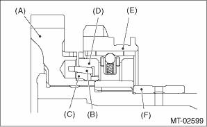
(A) | 1st driven gear |
(B) | Synchro cone |
(C) | Inner baulk ring |
(D) | Outer baulk ring |
(E) | Gear & hub |
(F) | 2nd driven gear bushing |
NOTE:
If necessary, use a new gear and hub assembly as a set, when replacing the gear or hub. Because these must engage at the specified point, avoid disassembly as much as possible. If it must be disassembled, mark the engaging point on the spline beforehand.
| ST1 499757002 | INSTALLER |
| ST2 899714110 | REMOVER |
 Assembly
MANUAL TRANSMISSION AND DIFFERENTIAL(5MT) > Drive Pinion Shaft AssemblyASSEMBLY1. Install the sleeve and the gear and hub assembly by matching the alignment marks.NOTE:• Make sure that there ...
 Inspection
MANUAL TRANSMISSION AND DIFFERENTIAL(5MT) > Drive Pinion Shaft AssemblyINSPECTIONDisassembled parts should be washed with cleaning solvent first, then inspected carefully.1. BearingReplace the bear ...
Other materials:
Dtc p2270 o2 sensor signal biased/stuck lean bank 1 sensor 2
ENGINE (DIAGNOSTICS)(H4DO) > Diagnostic Procedure with Diagnostic Trouble Code (DTC)DTC P2270 O2 SENSOR SIGNAL BIASED/STUCK LEAN BANK 1 SENSOR 2DTC detecting condition:Detected when two consecutive driving cycles with fault occur.CAUTION:After servicing or replacing faulty parts, perform Clear Me ...
Dtc b1808 short in passenger s airbag (to +b)
AIRBAG SYSTEM (DIAGNOSTICS) > Diagnostic Chart with Trouble CodeDTC B1808 SHORT IN PASSENGER’S AIRBAG (TO +B)Diagnosis start condition:Ignition voltage is 10 V to 16 V.DTC detecting condition:• Airbag main harness circuit is shorted to power supply.• Airbag module harness (passe ...
Installation
CONTINUOUSLY VARIABLE TRANSMISSION(TR580) > Oil PumpINSTALLATION1. Install the O-ring.NOTE:• Use new O-rings.• Apply CVTF to the O-ring.2. Install the plate and the oil pump.NOTE:Apply CVTF to the bolt.Tightening torque:8.5 N·m (0.9 kgf-m, 6.3 ft-lb)3. Install the oil pump chai ...
