Subaru Crosstrek Service Manual: Disassembly
CONTROL SYSTEMS > Select Lever
DISASSEMBLY
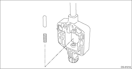
1. GRIP ASSY
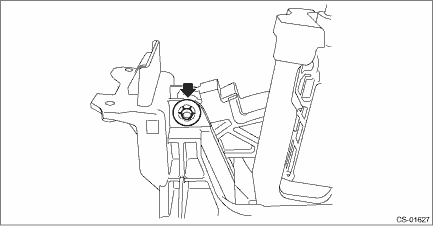
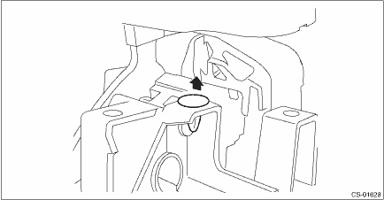
1. Remove the button assembly_AT.
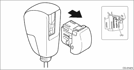
(A) | Claw |
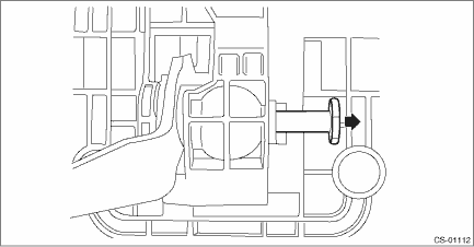
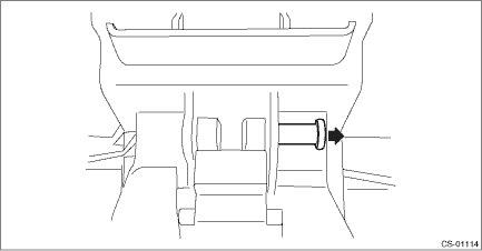
2. Remove the rod COMPL.
2. AT SELECT LEVER ASSEMBLY
1. Remove the spacer plate.
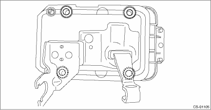
2. Remove the gasket.
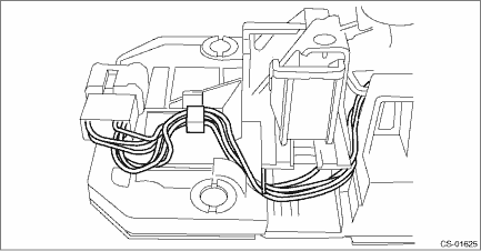
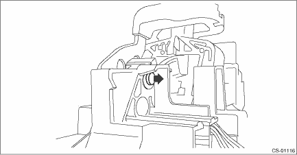
3. Insert a flat tip screwdriver with a thin tip under the connector and disconnect the harness connector from the plate COMPL.
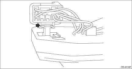
4. Remove the harness from the plate COMPL.
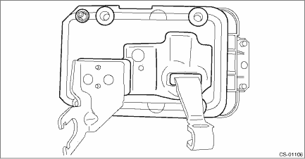
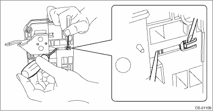
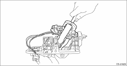
5. Raise the claw with a flat tip screwdriver with a thin tip and remove the solenoid unit.
6. Remove the terminal of the solenoid unit using a flat tip precision screwdriver with a tip width of 1.3 mm (0.05 in) or less, KTC connector terminal tool ECC-1T or equivalent.
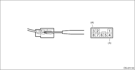
(A) | Solenoid unit terminals |
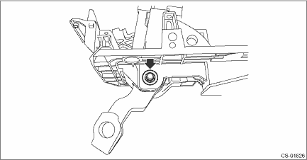
7. Remove the clamp push nut.
NOTE:
Replace the clamp push nut with a new part.
8. Pull out shaft control.
9. Remove the clamp push nut.
NOTE:
Replace the clamp push nut with a new part.
10. Pull out spacer pin guide.
11. Remove the clamp pin.
12. Remove the spacer pin guide.
13. Remove the select lever COMPL from the plate COMPL.
14. Remove the arm COMPL.
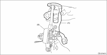
(A) | Arm COMPL |
(B) | Select lever COMPL |
15. Remove the plate guide from the select lever COMPL.
16. Remove the rod detent and detent spring from the select lever COMPL.
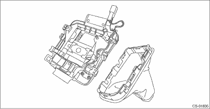
3. INDICATOR ASSY
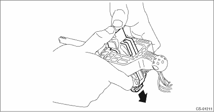
1. Remove the boot assembly from the indicator assembly.
CAUTION:
When removing the boot assembly, be careful not to damage the boot assembly claws and adjacent parts.
 Removal
CONTROL SYSTEMS > Select LeverREMOVAL1. Shift the select lever to “N” range.2. Disconnect the ground cable from battery. NOTE">NOTE:For model with battery sensor, disconnect th ...
 Inspection
CONTROL SYSTEMS > Select LeverINSPECTION1. Inspect the removed parts by comparing with new parts for deformation, damage and wear. Repair or replace if defective.2. Inspect the select lever assembl ...
Other materials:
Dtc p062f internal control module eeprom error
ENGINE (DIAGNOSTICS)(H4DO) > Diagnostic Procedure with Diagnostic Trouble Code (DTC)DTC P062F INTERNAL CONTROL MODULE EEPROM ERRORNOTE:For the diagnostic procedure, refer to DTC P0606. Diagnostic Procedure with Diagnostic Trouble Code (DTC) > DTC P0606 CONTROL MODULE PROCESSOR">1. OUT ...
Inspection
DIFFERENTIALS > Rear Differential (T-type)INSPECTIONWash all the disassembled parts clean, and examine them for wear, damage and other defects. Repair or replace the defective parts as necessary.1. Hypoid driven gear and drive pinion• If there is evidently an abnormal tooth contact, find ou ...
Assembly
STARTING/CHARGING SYSTEMS(H4DO) > GeneratorASSEMBLYAssemble in the reverse order of disassembly.NOTE:• Refer to component for tightening torque of each part. General Description > COMPONENT">• After assembling, manually turn the pulley to check that the rotor rotates smoot ...
