Subaru Crosstrek Service Manual: Diagnostics chart for security indicator light Inspection
IMMOBILIZER (DIAGNOSTICS) > Diagnostics Chart for Security Indicator Light
INSPECTION
1. CHECK SECURITY INDICATOR LIGHT CIRCUIT
CAUTION:
When the body integrated unit is replaced, registration of the immobilizer system is required. For details, refer to the “REGISTRATION MANUAL FOR IMMOBILIZER” provided as a separate volume.
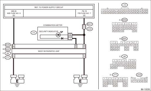
Wiring diagram:
Immobilizer system Immobilizer System > WIRING DIAGRAM">
| STEP | CHECK | YES | NO |
1.CHECK FUSE.
1) Remove the ignition key from ignition switch. Or, turn off the power.
2) Check the fuse (M/B No. 8).
Is the fuse OK?
Diagnostics Chart for Security Indicator Light > INSPECTION">Go to Step 2.
Replace the fuse. If the replaced fuse blows out easily, repair the short circuit in the harness between the fuse and body integrated unit.
2.CHECK SECURITY INDICATOR LIGHT.
1) Disconnect the connector from body integrated unit.
2) Connect the resistor (100 ?) between the body integrated unit connector terminal (i171) No. 26 and chassis ground.
Does the security indicator light illuminate?
Diagnostics Chart for Security Indicator Light > INSPECTION">Go to Step 3.
Diagnostics Chart for Security Indicator Light > INSPECTION">Go to Step 5.
3.CHECK BODY INTEGRATED UNIT GROUND CIRCUIT (OPEN CIRCUIT).
Measure the resistance between the body integrated unit connector terminal and chassis ground.
Connector & terminal
(B280) No. 1 — Chassis ground:
(i84) No. 1 — Chassis ground:
Is the resistance less than 10 ??
Diagnostics Chart for Security Indicator Light > INSPECTION">Go to Step 4.
Repair the open circuit of the body integrated unit ground circuit.
4.CHECK BODY INTEGRATED UNIT POWER SUPPLY CIRCUIT.
Measure the voltage between the body integrated unit connector terminal and chassis ground.
Connector & terminal
(B281) No. 7 (+) — Chassis ground (−):
(i84) No. 6 (+) — Chassis ground (−):
Is the voltage 10 V or more?
Replace the body integrated unit. Body Integrated Unit">
Check the harness for open or short circuit between body integrated unit and fuse.
5.CHECK COMBINATION METER CIRCUIT.
1) Remove the combination meter. Combination Meter">
2) Measure the voltage between combination meter connector terminal and chassis ground.
Connector & terminal
(i10) No. 40 (+) — Chassis ground (−):
Is the voltage 10 V or more?
Diagnostics Chart for Security Indicator Light > INSPECTION">Go to Step 6.
Check for an open or short circuit in the harness between the combination meter and fuse.
6.CHECK COMBINATION METER CIRCUIT (OPEN).
Measure the resistance between the body integrated unit connector terminal and combination meter connector terminal.
Connector & terminal
(i171) No. 26 — (i10) No. 1:
Is the resistance less than 10 ??
LED bulb is defective. Replace the combination meter case assembly. Combination Meter > DISASSEMBLY">
Repair the harness or connector.
2. CHECK KEY SWITCH CIRCUIT
CAUTION:
When the body integrated unit is replaced, registration of the immobilizer system is required. For details, refer to the “REGISTRATION MANUAL FOR IMMOBILIZER” provided as a separate volume.
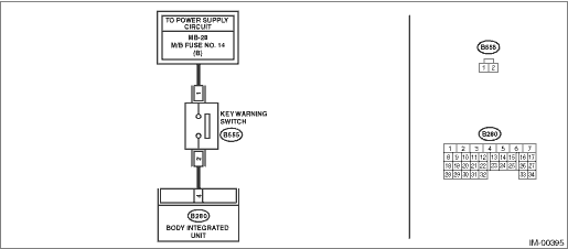
Wiring diagram:
Immobilizer system Immobilizer System > WIRING DIAGRAM">
| STEP | CHECK | YES | NO |
1.CHECK POWER SUPPLY CIRCUIT.
1) Disconnect the connector from key warning switch.
2) Measure the voltage between key warning switch connector terminal and chassis ground.
Connector & terminal
(B555) No. 1 (+) — Chassis ground (−):
Is the voltage 10 V or more?
Diagnostics Chart for Security Indicator Light > INSPECTION">Go to Step 2.
Check the harness for an open or short between the key warning switch and fuse.
2.CHECK KEY WARNING SWITCH.
1) Insert the ignition key in the ignition switch. (OFF or ACC)
2) Measure the resistance between key warning switch connector terminals.
Terminals
No. 1 — No. 2:
Is the resistance less than 1 ??
Diagnostics Chart for Security Indicator Light > INSPECTION">Go to Step 3.
Replace the key warning switch. Key Lock Cylinders">
3.CHECK KEY WARNING SWITCH.
1) Remove the ignition key from ignition switch.
2) Measure the resistance between key warning switch connector terminals.
Terminals
No. 1 — No. 2:
Is the resistance 1 M? or more?
Diagnostics Chart for Security Indicator Light > INSPECTION">Go to Step 4.
Replace the key warning switch. Key Lock Cylinders">
4.CHECK HARNESS BETWEEN KEY WARNING SWITCH AND BODY INTEGRATED UNIT (OPEN).
1) Disconnect the connector from body integrated unit.
2) Measure the resistance between key warning switch connector terminal and body integrated unit connector terminal.
Connector & terminal
(B555) No. 2 — (B280) No. 4:
Is the resistance less than 10 ??
Replace the body integrated unit. Body Integrated Unit">
Repair the harness between key warning switch and body integrated unit.
 Clear memory mode Operation
IMMOBILIZER (DIAGNOSTICS) > Clear Memory ModeOPERATIONNOTE:For detailed operation procedures, refer to “Application help”.1. ECM1. On «Start» display, select «Diagnosis».2. On «Veh ...
 Electrical component location Location
IMMOBILIZER (DIAGNOSTICS) > Electrical Component LocationLOCATION(1)Security indicator light (LED bulb)(3)Data link connector(5)Transponder(2)Body integrated unit(4)Antenna(6)Security control modul ...
Other materials:
Caution
EyeSight > General DescriptionCAUTION• Before disconnecting connectors of sensors or units, be sure to disconnect the ground cable from battery. When replacing the electrical parts provided with memory functions that store contents specified by a customer, record the memory contents before ...
Caution
EMISSION CONTROL (AUX. EMISSION CONTROL DEVICES)(H4DO) > General DescriptionCAUTION• Prior to starting work, pay special attention to the following:1. Always wear work clothes, a work cap, and protective shoes. Additionally, wear a helmet, protective goggles, etc. if necessary.2. Protect th ...
Dtc p0716 input/turbine shaft speed sensor "a" circuit range/performance
CONTINUOUSLY VARIABLE TRANSMISSION (DIAGNOSTICS) > Diagnostic Procedure with Diagnostic Trouble Code (DTC)DTC P0716 INPUT/TURBINE SHAFT SPEED SENSOR "A" CIRCUIT RANGE/PERFORMANCEDTC detecting condition:Immediately at fault recognitionTrouble symptom:• No lock-up occurs.• Sho ...
