Subaru Crosstrek Service Manual: Diagnostic procedure for subaru select monitor communication Communication for initializing impossible
ENGINE (DIAGNOSTICS)(H4DO) > Diagnostic Procedure for Subaru Select Monitor Communication
COMMUNICATION FOR INITIALIZING IMPOSSIBLE
DIAGNOSIS:
Open or short circuit in data link connector
TROUBLE SYMPTOM:
Subaru Select Monitor communication failure
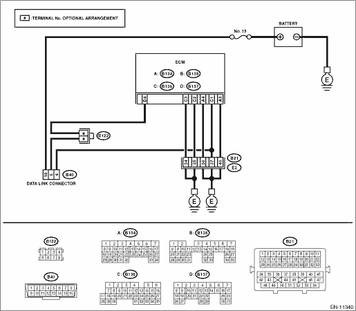
WIRING DIAGRAM:
Engine electrical system Engine Electrical System">
| STEP | CHECK | YES | NO |
1.CHECK POWER SUPPLY CIRCUIT.
Connect DST-i or general scan tool to data link connector.
Does DST-i or the general scan tool turn ON?
Diagnostic Procedure for Subaru Select Monitor Communication > COMMUNICATION FOR INITIALIZING IMPOSSIBLE">Go to Step 4.
Diagnostic Procedure for Subaru Select Monitor Communication > COMMUNICATION FOR INITIALIZING IMPOSSIBLE">Go to Step 2.
2.CHECK POWER SUPPLY CIRCUIT.
Measure the voltage between data link connector and chassis ground.
Connector & terminal
(B40) No. 16 (+) — Chassis ground (−):
Is the voltage 10 V or more?
Diagnostic Procedure for Subaru Select Monitor Communication > COMMUNICATION FOR INITIALIZING IMPOSSIBLE">Go to Step 3.
Repair the power supply circuit.
NOTE:
In this case, repair the following item:
• Open or ground short circuit of harness between battery and data link connector
• Blown out of fuse (M/B No. 13)
3.CHECK HARNESS BETWEEN DATA LINK CONNECTOR AND CHASSIS GROUND.
1) Turn the ignition switch to OFF.
2) Measure the resistance of harness between data link connector and chassis ground.
Connector & terminal
(B40) No. 4 — Chassis ground:
(B40) No. 5 — Chassis ground:
Is the resistance less than 5 ??
Repair the poor contact of data link connector.
Repair the harness and connector.
NOTE:
In this case, repair the following item:
• Open circuit in harness between ECM connector and data link connector
• Open circuit of harness between ECM connector and engine ground
• Poor contact of ECM connector
• Poor contact of coupling connector
4.CHECK HARNESS BETWEEN ECM AND DATA LINK CONNECTOR.
Measure the resistance between data link connector and chassis ground.
Connector & terminal
(B40) No. 7 — Chassis ground:
Is the resistance 1 M? or more?
Repair the poor contact of the ECM or data link connector.
Repair the short circuit to ground in harness between ECM connector and data link connector.
 Data link connector Note
ENGINE (DIAGNOSTICS)(H4DO) > Data Link ConnectorNOTEThis connector is used for Subaru Select Monitor.CAUTION:Do not connect any scan tools other than Subaru Select Monitor or general scan tool beca ...
 Drive cycle Procedure
ENGINE (DIAGNOSTICS)(H4DO) > Drive CyclePROCEDUREIt is necessary to perform the drive cycle listed below if DTC is not found in the Inspection Mode. It is possible to complete diagnosis of the DTC ...
Other materials:
Dtc c1232 rear right abs sensor signal
VEHICLE DYNAMICS CONTROL (VDC) (DIAGNOSTICS) > Diagnostic Procedure with Diagnostic Trouble Code (DTC)DTC C1232 REAR RIGHT ABS SENSOR SIGNALNOTE:For the diagnostic procedure, refer to “DTC C1242 REAR LEFT ABS SENSOR SIGNAL”. Diagnostic Procedure with Diagnostic Trouble Code (DTC) > ...
Child restraint systems
Infants and small children should always
be placed in an infant or child restraint
system in the rear seat while riding in the
vehicle. You should use an infant or child
restraint system that meets Federal Motor
Vehicle Safety Standards or Canada
Motor Vehicle Safety Standards, is compatib ...
Dtc b11f7 side impact deployment
AIRBAG SYSTEM (DIAGNOSTICS) > Diagnostic Chart with Trouble CodeDTC B11F7 SIDE IMPACT DEPLOYMENTDIAGNOSIS START CONDITION:Ignition voltage is 10 V to 16 V.DTC DETECTING CONDITION:This DTC is displayed when the side airbag module and curtain airbag module are deployed.Once this DTC is displayed, t ...
