Subaru Crosstrek Service Manual: Diagnostic procedure for subaru select monitor communication Communication for initializing impossible
CONTINUOUSLY VARIABLE TRANSMISSION (DIAGNOSTICS) > Diagnostic Procedure for Subaru Select Monitor Communication
COMMUNICATION FOR INITIALIZING IMPOSSIBLE
Diagnosis:
Defective harness connector
Trouble symptom:
Subaru Select Monitor communication failure
CAUTION:
Use the check board when measuring the TCM terminal voltage and resistance.
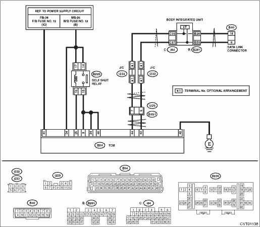
Wiring diagram:
CVT control system CVT Control System">

| STEP | CHECK | YES | NO |
1.CHECK IGNITION SWITCH.
Is the ignition switch ON?
Diagnostic Procedure for Subaru Select Monitor Communication > COMMUNICATION FOR INITIALIZING IMPOSSIBLE">Go to Step 2.
Turn the ignition switch to ON, and select the transmission using the Subaru Select Monitor.
2.CHECK BATTERY.
1) Turn the ignition switch to OFF.
2) Measure the battery voltage.
Is the voltage 11 V or more?
Diagnostic Procedure for Subaru Select Monitor Communication > COMMUNICATION FOR INITIALIZING IMPOSSIBLE">Go to Step 3.
Charge or replace the battery.
3.CHECK BATTERY TERMINAL.
Is there poor contact at battery terminal?
Replace or tighten the battery terminal.
Diagnostic Procedure for Subaru Select Monitor Communication > COMMUNICATION FOR INITIALIZING IMPOSSIBLE">Go to Step 4.
4.CHECK INSTALLATION OF TCM CONNECTOR.
Turn the ignition switch to OFF.
Is the TCM connector inserted into the TCM until the clamp locks?
Diagnostic Procedure for Subaru Select Monitor Communication > COMMUNICATION FOR INITIALIZING IMPOSSIBLE">Go to Step 5.
Insert the TCM connector to TCM.
5.CHECK LAN SYSTEM.
Perform the diagnosis for LAN system. Basic Diagnostic Procedure">
Is there any fault in LAN system?
Perform the diagnosis according to DTC for LAN system. List of Diagnostic Trouble Code (DTC)">
Diagnostic Procedure for Subaru Select Monitor Communication > COMMUNICATION FOR INITIALIZING IMPOSSIBLE">Go to Step 6.
6.CHECK SUBARU SELECT MONITOR COMMUNICATION.
1) Turn the ignition switch to ON.
2) Check whether communication to transmission system can be executed normally.
Is «Select Function» displayed?
Check DTC of TCM. Read Diagnostic Trouble Code (DTC)">
Diagnostic Procedure for Subaru Select Monitor Communication > COMMUNICATION FOR INITIALIZING IMPOSSIBLE">Go to Step 7.
7.CHECK POWER SUPPLY CIRCUIT.
1) Turn the ignition switch to OFF.
2) Disconnect the TCM connector.
3) Turn the ignition switch to ON. (Engine OFF)
4) Measure the ignition power supply voltage between TCM connector and chassis ground.
Connector & terminal
(B54) No. 8 (+) — Chassis ground (−):
(B54) No. 24 (+) — Chassis ground (−):
(B54) No. 34 (+) — Chassis ground (−):
(B54) No. 40 (+) — Chassis ground (−):
(B54) No. 41 (+) — Chassis ground (−):
Is the voltage 10 — 13 V?
Diagnostic Procedure for Subaru Select Monitor Communication > COMMUNICATION FOR INITIALIZING IMPOSSIBLE">Go to Step 8.
Repair the open circuit of harness between TCM and battery.
8.CHECK HARNESS CONNECTOR BETWEEN TCM AND CHASSIS GROUND.
1) Turn the ignition switch to OFF.
2) Measure the resistance of harness between TCM connector and chassis ground.
Connector & terminal
(B54) No. 42 — Chassis ground:
Is the resistance less than 10 ??
Diagnostic Procedure for Subaru Select Monitor Communication > COMMUNICATION FOR INITIALIZING IMPOSSIBLE">Go to Step 9.
Repair the open circuit of the TCM ground circuit and poor contact of connector.
9.CHECK POOR CONTACT OF CONNECTOR.
Is there poor contact of control module power supply, ground circuit and data link connector?
Repair the connector.
Replace the TCM. Transmission Control Module (TCM)">
 Clear memory mode Operation
CONTINUOUSLY VARIABLE TRANSMISSION (DIAGNOSTICS) > Clear Memory ModeOPERATION1. On «Start» display, select «Diagnosis».2. On «Vehicle selection» display, input the vehicle information and sel ...
 Diagnostic procedure without diagnostic trouble code (dtc) Check shift indicator
CONTINUOUSLY VARIABLE TRANSMISSION (DIAGNOSTICS) > Diagnostic Procedure without Diagnostic Trouble Code (DTC)CHECK SHIFT INDICATORDiagnosis:• CAN communication is abnormal with the combinatio ...
Other materials:
Activation of malfunction indicator light
ENGINE (DIAGNOSTICS)(H4DO) > Malfunction Indicator LightACTIVATION OF MALFUNCTION INDICATOR LIGHT1. When the ignition switch is turned to ON (engine OFF), the malfunction indicator light (A) in the combination meter illuminates.NOTE:If the malfunction indicator light does not illuminate, perform ...
Dtc p0843 transmission fluid pressure sensor/switch "a" circuit high
CONTINUOUSLY VARIABLE TRANSMISSION (DIAGNOSTICS) > Diagnostic Procedure with Diagnostic Trouble Code (DTC)DTC P0843 TRANSMISSION FLUID PRESSURE SENSOR/SWITCH "A" CIRCUIT HIGHDTC detecting condition:Immediately at fault recognitionTrouble symptom:Shift characteristics malfunctionCAUTION: ...
Inspection
EyeSight > Relay and FuseINSPECTION1. CHECK FUSE1. Remove the fuse and inspect visually.2. If the fuse is blown out, replace the fuse.NOTE:If the fuse is blown again, check the system wiring harness.2. CHECK RELAY1. Measure the resistance between relay terminals.Terminal No.Inspection conditionsS ...
