Subaru Crosstrek Service Manual: Control module i/o signal Electrical specification
INSTRUMENTATION/DRIVER INFO (DIAGNOSTICS) > Control Module I/O Signal
ELECTRICAL SPECIFICATION
• Combination meter
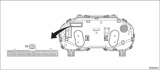
Terminal No. | Content | Terminal No. | Content |
1 | Security indicator | 27 | Ambient sensor |
2 | Charge warning light | 28 | UART (MFD) |
3 | Oil pressure warning light | 29 | Steering switch (+) |
4 | RH turn indicator | 30 | Pedestrian alert device |
6 | LH turn indicator | 32 | CAN communication line (−) |
8 | Auto headlight beam leveler warning light | 33 | CAN communication line (+) |
15 | Driver’s seat belt switch | 36 | Ambient sensor GND |
16 | Passenger’s seat belt switch | 37 | Fuel level sensor GND |
20 | Ignition power supply | 38 | GND |
21 | Washer fluid level sensor | 39 | Backup ignition power supply |
23 | Brake fluid level switch | 40 | Battery power supply |
25 | Fuel level sensor | — | — |
Terminal No. | Item | Measuring condition | Standard |
1 ←> Chassis ground | Voltage | Security indicator light off > on | 0 V > 10 — 14 V |
2 ←> Chassis ground | Voltage | Charge warning light off > on | 0 V > 10 — 14 V |
3 ←> Chassis ground | Voltage | Oil pressure warning light off > on | 0 V > 10 — 14 V |
4 ←> Chassis ground | Voltage | RH turn indicator off > on | 0 V > 10 — 14 V |
6 ←> Chassis ground | Voltage | LH turn indicator off > on | 0 V > 10 — 14 V |
8 ←> Chassis ground | Voltage | Auto headlight beam leveler warning light off > on | 0 V > 10 — 14 V |
15 ←> Chassis ground | Resistance | Driver’s seat belt switch ON | Less than 1 ? |
16 ←> Chassis ground | Resistance | Passenger’s seat belt switch ON | Less than 1 ? |
20 ←> Chassis ground | Voltage | IG OFF > ON | 0 V > 10 — 14 V |
21 ←> Chassis ground | — | Washer fluid level sensor | — |
23 ←> Chassis ground | — | Brake fluid level switch | — |
25 ←> 37 | Resistance | Fuel level sensor | 10 — 600 ? |
27 ←> 36 | Resistance | Ambient sensor | 1 — 35 k? |
28 (UART) ←> Chassis ground | — | Cannot be measured | — |
32 (CAN−) ←> Chassis ground | — | Cannot be measured | — |
33 (CAN+) ←> Chassis ground | — | Cannot be measured | — |
34 ←> Chassis ground | Resistance | Always | Less than 1 ? |
35 ←> Chassis ground | Resistance | Always | Less than 1 ? |
36 ←> Chassis ground | Resistance | Always | Less than 1 ? |
37 ←> Chassis ground | Resistance | Always | Less than 1 ? |
38 ←> Chassis ground | Resistance | Always | Less than 1 ? |
39 ←> Chassis ground | Resistance | Always | Less than 1 ? |
40 ←> Chassis ground | Voltage | Always | 10 — 14 V |
• MFD
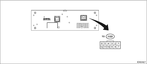
Terminal No. | Content | Terminal No. | Content |
1 | Battery power supply | 7 | — |
2 | GND | 8 | — |
3 | Ignition power supply | 9 | UART (meter) |
4 | Switch communication line (−) | 10 | Passenger’s airbag ON |
5 | CAN communication line (−) | 11 | Passenger’s airbag OFF |
6 | CAN communication line (+) | 12 | Switch communication line (+) |
Terminal No. | Item | Measuring condition | Standard |
1 (+B) ←> Chassis ground | Voltage | Always | 10 — 14 V |
2 (GND) ←> Chassis ground | Resistance | Always | Less than 1 ? |
3 (IGN) ←> Chassis ground | Voltage | IG OFF > ON | 0 V > 10 — 14 V |
4 (STR−) ←> Chassis ground | — | Cannot be measured (switch communication line) | — |
5 (CAN−) ←> Chassis ground | — | Cannot be measured (CAN communication line) | — |
6 (CAN+) ←> Chassis ground | — | Cannot be measured (CAN communication line) | — |
9 (UART) ←> Chassis ground | — | Cannot be measured (meter communication line) | — |
10 ←> Chassis ground | Voltage | Passenger’s airbag ON indicator (when illuminating) | Less than 1 V |
11 ←> Chassis ground | Voltage | Passenger’s airbag OFF indicator (when illuminating) | Less than 1 V |
12 (STR+) ←> Chassis ground | — | Cannot be measured (switch communication line) | — |
 Clear memory mode Operation
INSTRUMENTATION/DRIVER INFO (DIAGNOSTICS) > Clear Memory ModeOPERATION1. COMBINATION METER1. On «Start» display, select «Diagnosis».2. On «Vehicle selection» display, input the target vehicle ...
 Electrical component location Location
INSTRUMENTATION/DRIVER INFO (DIAGNOSTICS) > Electrical Component LocationLOCATION(1)Combination meter(2)MFD(3)Data link connector ...
Other materials:
Diagnostics with phenomenon Inspection
AUTO HEADLIGHT BEAM LEVELER SYSTEM (DIAGNOSTICS) > Diagnostics with PhenomenonINSPECTION1. BEAM LEVEL CONTROL DOES NOT FUNCTIONCAUTION:• Before performing diagnosis, check the fuse in this circuit.• Initialization is required after replacing the auto headlight beam leveler CM.Wiring d ...
Tilting moonroof
Raise
Lower
The tilting function is activated only when
the moonroof is fully closed.
To raise:
Press the rear side of the "UP/DOWN"
switch momentarily. The moonroof raises
completely.
To lower:
Press and hold the front side of the "UP/
DOWN" switch until the preferred positi ...
Removal
DIFFERENTIALS > Rear Differential Front MemberREMOVAL1. Disconnect the ground cable from battery.2. Lift up the vehicle.3. Support the rear differential using transmission jack, and then remove the rear differential front member.(A)Rear differential front member ...
