Subaru Crosstrek Service Manual: Control module i/o signal Electrical specification
BODY CONTROL SYSTEM (DIAGNOSTICS) > Control Module I/O Signal
ELECTRICAL SPECIFICATION
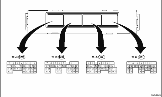
Description | Terminal No. | Signal (V or ?) | Note |
Ignition switch ON (Engine OFF) | |||
Ignition power supply (rear wiper) | A5 ←> Chassis ground | Less than 1.5 V > 10 — 13 V | Ignition switch OFF > ON |
Battery power supply (shift lock/key lock) | B6 ←> Chassis ground | 10 — 13 V | Always |
Battery power supply (door lock) | D1 ←> Chassis ground | 10 — 13 V | Always |
Battery power supply (control) | C6 ←> Chassis ground | 10 — 13 V | Always |
Ground | A1 ←> Chassis ground | Less than 1.5 V | Always |
C1 ←> Chassis ground | |||
Battery power supply (back-up) | B7 ←> Chassis ground | 10 — 13 V | Always |
Ignition power supply | B3 ←> Chassis ground | Less than 1.5 V > 10 — 13 V | Ignition switch OFF > ON |
ACC power supply | A32 ←> Chassis ground | Less than 1.5 V > 10 — 13 V | Ignition switch OFF > Accessory ON |
Key-in switch | A4 ←> Chassis ground | Less than 1.5 V > 10 — 13 V | Key is inserted (model without the keyless access with push button start system) |
ACC input | A4 ←> Chassis ground | Less than 1.5 V > 10 — 13 V | ACC ON (model with the keyless access with push button start system) |
P range SW | B18 ←> Chassis ground | Less than 1.5 V > 8 V or more | P range to other than P range |
Stop light SW | A10 ←> Chassis ground | Less than 1.5 V > 8 V or more | Stop light switch OFF > ON |
Door SW (driver’s) | C14 ←> Chassis ground | 8 V or more > less than 1.5 V | Front right door closed > open |
Door SW (passenger’s) | C13 ←> Chassis ground | 8 V or more > less than 1.5 V | Front left door closed > open |
Door SW (rear right) | C25 ←> Chassis ground | 8 V or more > less than 1.5 V | Rear right door closed > open |
Door SW (rear left) | C24 ←> Chassis ground | 8 V or more > less than 1.5 V | Rear left door closed > open |
Rear gate SW/trunk SW | C33 ←> Chassis ground | 8 V or more > less than 1.5 V | Rear gate/trunk closed > open |
Opener SW (trunk/rear gate) | C10 ←> Chassis ground | 8 V or more > less than 1.5 V | Rear gate/trunk opener switch ON |
Manual switch (LOCK) | C9 ←> Chassis ground | 8 V or more > less than 1.5 V | Door lock switch ON |
Manual switch (UNLOCK) | C20 ←> Chassis ground | 8 V or more > less than 1.5 V | Door unlock switch ON |
Lighting AUTO | B16 ←> Chassis ground | 8 V or more > less than 1.5 V | Switch at AUTO position |
Lighting II | A34 ←> Chassis ground | 8 V or more > less than 1.5 V | Switch at II position |
B34 ←> Chassis ground | |||
Lighting I | B17 ←> Chassis ground | 8 V or more > less than 1.5 V | Switch at I position |
Dimmer passing | B25 ←> Chassis ground | 8 V or more > less than 1.5 V | Switch at passing position |
Dimmer Hi beam | B15 ←> Chassis ground | 8 V or more > less than 1.5 V | Switch at Hi beam position |
Front fog light SW | B26 ←> Chassis ground | 8 V or more > less than 1.5 V | Front fog light switch ON |
Illumination sensor power supply | B1 ←> A29 | Less than 1.5 V > 4.5 V or more | Ignition switch OFF > ON |
Illumination sensor signal | A19 | 0.2 — 4.5 V | Ignition switch OFF > ON |
Ground (illumination sensor) | A29 ←> Chassis ground | Less than 1.5 V | Always |
Rear wiper SW ON | A12 ←> Chassis ground | 8 V or more > less than 1.5 V | Switch at ON position |
Rear wiper SW INT | A22 ←> Chassis ground | 8 V or more > less than 1.5 V | Switch at INT position |
Rear washer SW | A30 ←> Chassis ground | 8 V or more > less than 1.5 V | Switch at ON position |
Illumination SW (Vi1) | D12 ←> Chassis ground | Approx. 5 V | While clearance light illuminates |
Illumination SW (Vi2) | D22 ←> Chassis ground | 0.5 — 4.8 V | |
Illumination SW (Vi3) | D28 ←> Chassis ground | Less than 1.5 V | Always |
Bright SW | C21 ←> Chassis ground | 8 V or more > less than 1.5 V | Switch at ON position |
Reverse SW (MT) | B12 ←> Chassis ground | Less than 1.5 V > 8 V or more | Reverse SW ON |
Impact sensor | A11 ←> Chassis ground | 8 V or more | Apply an impact |
Hi-speed CAN communication circuit 1 (Hi) | B20 | Serial communication | Except for sleep status*1 |
Hi-speed CAN communication circuit 1 (Lo) | B28 | ||
Hi-speed CAN communication circuit 2 (Hi) | C27 | Serial communication | Except for sleep status*1 |
Hi-speed CAN communication circuit 2 (Lo) | C35 | ||
Immobilizer antenna (B) | B22 | Serial communication | Communication with ignition key in progress (Without keyless access with push button start system) |
Immobilizer antenna (A) | B10 | ||
Immobilizer antenna amplifier GND | B30 ←> Chassis ground | Less than 1.5 V | Always (Without keyless access with push button start system) |
Immobilizer antenna amplifier power supply | B2 ←> B30 | 4.5 — 5.5 V | Communication with ignition key in progress (Without keyless access with push button start system) |
Security UART | A21 | Serial communication | Always (Without keyless access with push button start system) |
Front wiper return | A2 ←> Chassis ground | 8 V | When front wiper is operated |
Door UNLOCK (driver’s seat) output | D4 ←> Chassis ground | Less than 0.5 V > 8 V or more | When driver’s side door unlock is output |
Keyless entry / TPMS communication circuit | D11 | Serial communication | When door lock/unlock is operated with the keyless transmitter, or when TPMS is operated |
Rear defogger switch | C18 ←> Chassis ground | Less than 1.5 V > 8 V or more | When the rear defogger switch is ON |
Parking brake switch | C32 ←> Chassis ground | 8 V or more > less than 1.5 V | When parking brake is ON |
Shift lock solenoid | B5 ←> Chassis ground | Less than 1.5 V > 8 V or more | When shift lock is operating (AT models) |
Key lock solenoid | B4 ←> Chassis ground | Less than 1.5 V > 8 V or more | LOCK status is ON (AT model without the keyless access with push button start system) |
Rear wiper ON output | A7 ←> Chassis ground | Less than 0.5 V > 8 V or more | Rear wiper operation in progress |
Rear wiper return | A6 ←> Chassis ground | Less than 0.5 V > 8 V or more | Rear wiper operation in progress |
Door LOCK output | D2 ←> Chassis ground | Less than 0.5 V > 8 V or more | When LOCK signal is output |
Door UNLOCK output | D3 ←> Chassis ground | Less than 0.5 V > 8 V or more | When UNLOCK signal is output |
Rear gate/trunk UNLOCK output | D7 ←> Chassis ground | Less than 0.5 V > 8 V or more | When UNLOCK signal is output |
Lighting relay power supply | A3 ←> Chassis ground | 10 — 13 V | ACC or key-in SW ON |
B19 ←> Chassis ground | 10 — 13 V | ACC or key-in SW ON | |
Lighting relay Hi output | A17 ←> Chassis ground | 8 V or more > less than 1.0 V | Dimmer SW at Hi position |
Lighting relay Lo output | B35 ←> Chassis ground | 8 V or more > less than 1.0 V | Lighting II SW at ON position |
Lighting Lo relay output 2 | A27 ←> Chassis ground | 8 V or more > less than 1.0 V | Lighting II SW at ON position |
Lighting relay I output | A16 ←> Chassis ground | 8 V or more > less than 1.0 V | Lighting I SW at ON position |
Front fog light output | A15 ←> Chassis ground | 8 V or more > less than 1.0 V | Front fog light SW at ON position |
DRL cancel output | D10 ←> Chassis ground | 8 V or more > less than 1.0 V | Headlight switch ON or Hi beam ON, passing switch ON |
Illumination output | B8 | Pulse output | Illumination ON |
C16 | Pulse output | Illumination ON | |
Key ring illumination | A25 | Pulse output | Illumination ON (Without keyless access with push button start system) |
Room light output | C4 | Pulse output | Room light ON (doors interlocked) |
Map light output | D8 | Pulse output | Map light ON (keyless answer-back, etc.) |
Luggage/trunk light output | C3 | Pulse output | Luggage/trunk at open state |
Rear defogger relay output | A26 ←> Chassis ground | 8 V or more > less than 1.0 V | Rear defogger SW ON |
Wiper deicer relay output | D9 ←> Chassis ground | 8 V or more > less than 1.0 V | Wiper deicer SW ON |
Turn/hazard output | D18 ←> Chassis ground | 8 V or more > less than 1.0 V | When answer-back is output |
Security horn output | A24 ←> Chassis ground | 8 V or more > less than 1.0 V | When security is operating |
Security light | D26 | Pulse control | When security light is illuminating |
Answer-back buzzer output | A20 ←> Chassis ground | 8 V or more > less than 1.0 V | When answer-back operates |
Immobilizer communication | A31 | Serial communication | (Models without the keyless access with push button start system) |
Turn signal RH | B9 ←> Chassis ground | 8 V or more > less than 1.5 V | When turn signal switch RH is ON |
Drive mode SW (Eco/X mode) | B14 ←> Chassis ground | 8 V or more > less than 1.5 V | Mode SW is turned OFF > ON |
Turn signal LH | B21 ←> Chassis ground | 8 V or more > less than 1.5 V | When turn signal switch LH is ON |
Accessory connector | B29 ←> Chassis ground | 8 V or more > less than 1.5 V | Rear gate/trunk closed > open |
Door lock status SW (Driver’s) | C12 ←> Chassis ground | 8 V or more > less than 1.5 V | Driver’s door inner remote lock > unlock |
Door lock status SW (Passenger’s) | C23 ←> Chassis ground | 8 V or more > less than 1.5 V | Passenger’s door inner remote lock > unlock |
SRF OFF SW input | D14 ←> Chassis ground | 8 V or more > less than 1.5 V | When SRF OFF SW is pressed |
LIN communication line | D16 | Serial communication | Except for sleep status*1 |
SRF relay output (R) | D20 ←> Chassis ground | Less than 1.5 V > 8 V or more | When SRF RH FOG is operating |
SRF relay output (L) | D21 ←> Chassis ground | Less than 1.5 V > 8 V or more | When SRF LH FOG is operating |
*1: For CAN sleep state, hold on for approx. one minute with ignition OFF and the doors, trunk, and rear gate all closed.
 Clear memory mode Operation
BODY CONTROL SYSTEM (DIAGNOSTICS) > Clear Memory ModeOPERATION1. On «Start» display, select «Diagnosis».2. On «Vehicle selection» display, input the target vehicle information and select «Co ...
 Electrical component location Location
BODY CONTROL SYSTEM (DIAGNOSTICS) > Electrical Component LocationLOCATION(1)Body integrated unit(2)Data link connector ...
Other materials:
Caution
STARTING/CHARGING SYSTEMS(H4DO) > General DescriptionCAUTION• Prior to starting work, pay special attention to the following:1. Always wear work clothes, a work cap, and protective shoes. Additionally, wear a helmet, protective goggles, etc. if necessary.2. Protect the vehicle using a seat ...
Dtc p0456 evap system (cpc) leak detected (very small leak)
ENGINE (DIAGNOSTICS)(H4DO) > Diagnostic Procedure with Diagnostic Trouble Code (DTC)DTC P0456 EVAP SYSTEM (CPC) LEAK DETECTED (VERY SMALL LEAK)NOTE:For the diagnostic procedure, refer to DTC P0455. Diagnostic Procedure with Diagnostic Trouble Code (DTC) > DTC P0455 EVAP SYSTEM (CPC) LEAK DETE ...
Selection of manual mode
With the vehicle either moving or stationary,
move the select lever from the "D"
position to the "M" position to select the
manual mode.
Type A
Upshift indicator
Downshift indicator
Gear position indicator
Type B
Upshift indicator
Downshift indicator
Gear position indi ...
