Subaru Crosstrek Service Manual: Component
HVAC SYSTEM (HEATER, VENTILATOR AND A/C) > General Description
COMPONENT
1. HEATER AND COOLING UNIT
• Manual A/C model
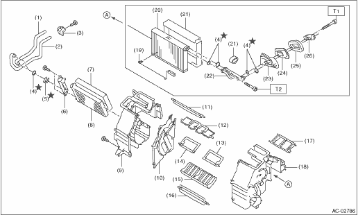
(1) | Pipe - inlet | (11) | Shutter - defroster | (21) | Packing - evaporator core |
(2) | Pipe - outlet | (12) | Shutter - vent | (22) | Pipe - evaporator core |
(3) | Clamp - pipe | (13) | Shutter - air mix RH | (23) | Case - expansion valve |
(4) | Seal O-ring | (14) | Shutter - air mix LH | (24) | Seal - cooling |
(5) | Clamp | (15) | Guide - heater unit | (25) | Packing - heater unit |
(6) | Plate - heater core | (16) | Shutter - foot | (26) | Expansion valve - cooling |
(7) | Packing - heater core | (17) | Case - vent duct | ||
(8) | Heater core | (18) | Case - heater unit UPR RH | Tightening torque: N·m (kgf-m, ft-lb) | |
(9) | Case - heater unit UPR LH | (19) | Thermostat - cooling | T1: | 5.0 (0.51, 3.7) |
(10) | Plate CTR | (20) | Evaporator ASSY - cooling | T2: | 6.7 (0.68, 4.9) |
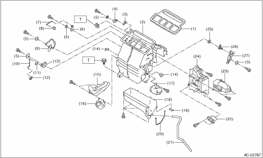
(1) | Packing - heater unit | (11) | Clip | (21) | Hose - drain |
(2) | Case - heater unit | (12) | Lever - foot | (22) | Resistor |
(3) | Lever - defroster | (13) | Lever - foot sub | (23) | Cover |
(4) | Lever - defroster sub | (14) | Clamp - cable | (24) | Cover - heater unit |
(5) | Washer - heater | (15) | Cover - heater pipe | (25) | Spring - heater unit |
(6) | Lever - ventilator sub | (16) | Duct - foot LH | (26) | Lever A |
(7) | Rod - ventilator | (17) | Duct - foot RH | (27) | Lever B |
(8) | Lever - ventilator door | (18) | Case - heater LWR | ||
(9) | Lever - mode | (19) | Clip - case | Tightening torque: N·m (kgf-m, ft-lb) | |
(10) | Rod - foot | (20) | Packing - evaporator cover | T: | 7.5 (0.76, 5.5) |
• Auto A/C model
(1) | Pipe - inlet | (11) | Shutter - defroster | (21) | Packing - evaporator core |
(2) | Pipe - outlet | (12) | Shutter - vent | (22) | Pipe - evaporator core |
(3) | Clamp - pipe | (13) | Shutter - air mix RH | (23) | Case - expansion valve |
(4) | Seal O-ring | (14) | Shutter - air mix LH | (24) | Seal - cooling |
(5) | Clamp | (15) | Guide - heater unit | (25) | Packing - heater unit |
(6) | Plate - heater core | (16) | Shutter - foot | (26) | Expansion valve - cooling |
(7) | Packing - heater core | (17) | Case - vent duct | ||
(8) | Heater core | (18) | Case - heater unit UPR RH | Tightening torque: N·m (kgf-m, ft-lb) | |
(9) | Case - heater unit UPR LH | (19) | Thermostat - cooling | T1: | 5.0 (0.51, 3.7) |
(10) | Plate CTR | (20) | Evaporator ASSY - cooling | T2: | 6.7 (0.68, 4.9) |
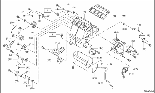
(1) | Packing - heater unit | (13) | Lever - foot sub | (25) | Spring - heater unit |
(2) | Case - heater unit | (14) | Harness - heater unit | (26) | Lever - air mix |
(3) | Lever - defroster | (15) | Cover - heater pipe | (27) | Rod - air mix |
(4) | Lever - defroster sub | (16) | Duct - foot LH | (28) | Motor - actuator mix RH |
(5) | Washer - heater | (17) | Duct - foot RH | (29) | Rod - mode |
(6) | Lever - ventilator sub | (18) | Case - heater LWR | (30) | Motor - actuator mode |
(7) | Rod - ventilator | (19) | Clip - case | (31) | Aspirator - heater unit |
(8) | Lever - ventilator door | (20) | Packing - evaporator cover | (32) | Aspirator hose |
(9) | Lever - mode | (21) | Hose - drain | (33) | Motor - actuator mix LH (dual A/C model) |
(10) | Rod - foot | (22) | Power transistor | ||
(11) | Clip | (23) | Cover | Tightening torque: N·m (kgf-m, ft-lb) | |
(12) | Lever - foot | (24) | Cover - heater unit | T: | 7.5 (0.76, 5.5) |
2. BLOWER MOTOR UNIT
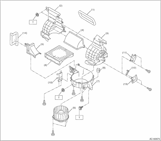
(1) | Packing - blower | (7) | Case lower - blower | (13) | Motor - actuator blower (manual A/C model) |
(2) | Case - blower intake LH | (8) | Blower motor relay | (14) | Packing |
(3) | Case - blower intake RH | (9) | Blower - motor | ||
(4) | Shutter - blower | (10) | Bracket | Tightening torque: N·m (kgf-m, ft-lb) | |
(5) | Case upper - blower | (11) | Motor - actuator blower (auto A/C model) | T: | 7.5 (0.76, 5.5) |
(6) | Filter kit | (12) | Lever | ||
3. CONTROL PANEL
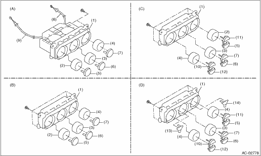
(A) | Manual A/C model | (C) | Single auto A/C model (with high grade MFD) | (D) | Dual auto A/C model |
(B) | Single auto A/C model (with standard MFD) | ||||
(1) | Control case | (6) | FRESH/RECIRC switch | (11) | Defroster switch |
(2) | Air flow control dial | (7) | A/C switch | (12) | OFF switch |
(3) | Fan dial | (8) | Temperature control cable | (13) | Air flow control switch |
(4) | Temperature adjustment dial | (9) | Air flow control cable | (14) | Dual switch |
(5) | Rear window defogger switch | (10) | AUTO switch |
4. AIR CONDITIONING UNIT
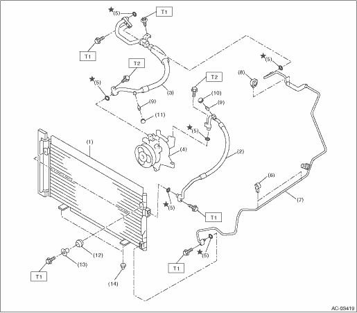
(1) | Condenser ASSY - air conditioner | (7) | Pipe - evaporator cooling | (13) | Spacer |
(2) | Hose - pressure discharge | (8) | Clip | (14) | Bushing - condenser |
(3) | Hose - pressure suction | (9) | Valve - hose pressure | ||
(4) | Compressor ASSY | (10) | Cap - hose pressure discharge | Tightening torque: N·m (kgf-m, ft-lb) | |
(5) | Seal O-ring | (11) | Cap - hose pressure suction | T1: | 7.5 (0.76, 5.5) |
(6) | Clip - pipe | (12) | Grommet | T2: | 10 (1.02, 7.4) |
5. HEATER HOSE
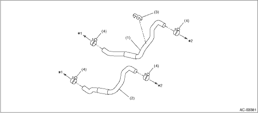
(1) | Hose - heater outlet | (3) | Clip | (4) | Clamp |
(2) | Hose - heater inlet | ||||
*1: Engine side *2: Heater core side | |||||
6. COMPRESSOR
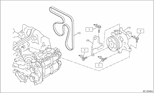
(1) | Compressor ASSY | (3) | Hanger - engine front | Tightening torque: N·m (kgf-m, ft-lb) | |
(2) | V-belt (6 PK) | T: | 36 (3.67, 26.6) | ||
*: Tighten the compressor in the numerical order as shown in the figure. | |||||
7. HEATER DUCT
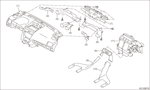
(1) | Panel COMPL - instrument | (5) | Duct - side defroster RH | (9) | Duct - rear heater LH |
(2) | Duct - side defroster LH | (6) | Duct - side ventilation RH | (10) | Duct - rear heater RH |
(3) | Duct - side ventilation LH | (7) | Nozzle - front defroster | (11) | Heater and cooling unit ASSY |
(4) | Duct - center vent | (8) | Duct - rear heater CTR |
 Specification
HVAC SYSTEM (HEATER, VENTILATOR AND A/C) > General DescriptionSPECIFICATION1. HEATER SYSTEMItemSpecificationsConditionHeating capacity5.0 kW (4,299 kcal/h, 17,059 BTU/h) or more• Air flow con ...
 Location
HVAC SYSTEM (HEATER, VENTILATOR AND A/C) > General DescriptionLOCATIONRefer to “LOCATION” for “HVAC SYSTEM (AUTO A/C) (DIAGNOSTICS)” section. Electrical Component Location ...
Other materials:
Selecting audible signal operation (models without "keyless access with
push-button start system")
Using an electronic chirp, the system will
give you an audible signal when the doors
lock and unlock. If desired, you may turn
the audible signal off.
Perform the following steps to deactivate
the audible signal. You can also use the
same steps to restore the function.
1. Sit in the drive ...
Dtc p0131 a/f / o2 sensor circuit low voltage bank 1 sensor 1
ENGINE (DIAGNOSTICS)(H4DO) > Diagnostic Procedure with Diagnostic Trouble Code (DTC)DTC P0131 A/F / O2 SENSOR CIRCUIT LOW VOLTAGE BANK 1 SENSOR 1DTC detecting condition:Immediately at fault recognitionCAUTION:After servicing or replacing faulty parts, perform Clear Memory Mode Clear Memory Mode ...
Inspection
CONTINUOUSLY VARIABLE TRANSMISSION(TR580) > Secondary Pressure SensorINSPECTION1. Start and warm up the engine.2. Depress the brake pedal, and shift the select lever to “D” range.3. Shift the select lever to “P” or “N” range.4. Depress the brake pedal and hold ...
