Subaru Crosstrek Service Manual: Component
CONTROL SYSTEMS > General Description
COMPONENT
1. AT SELECT LEVER
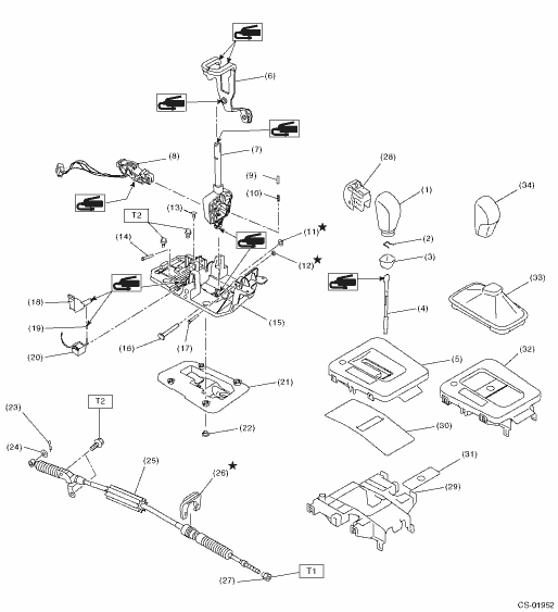
(1) | Grip sub ASSY (model with gate shifter) | (14) | Spacer pin guide | (27) | Nut |
(2) | Clamp grip pin | (15) | Plate COMPL | (28) | Button ASSY-AT |
(3) | Cover grip AT (model with gate shifter) | (16) | Shaft control | (29) | Housing |
(4) | Rod COMPL | (17) | Spacer pin guide | (30) | Blind A (model with gate shifter) |
(5) | Indicator cover (model with gate shifter) | (18) | Rod shift lock | (31) | Blind B (model with gate shifter) |
(6) | Arm COMPL | (19) | Cushion solenoid | (32) | Indicator assembly (model with boot shifter) |
(7) | Select lever COMPL | (20) | Solenoid unit | (33) | Boot ASSY (model with boot shifter) |
(8) | Plate guide | (21) | Gasket | (34) | Grip sub ASSY (model with boot shifter) |
(9) | Rod detent | (22) | Spacer plate | ||
(10) | Detent spring | (23) | Snap pin | Tightening torque: N·m (kgf-m, ft-lb) | |
(11) | Clamp push nut | (24) | Washer | T1: | 7.5 (0.8, 5.5) |
(12) | Clamp push nut | (25) | Select cable | T2: | 18 (1.8, 13.3) |
(13) | Clamp pin | (26) | Clamp | ||
2. 5MT GEAR SHIFT LEVER
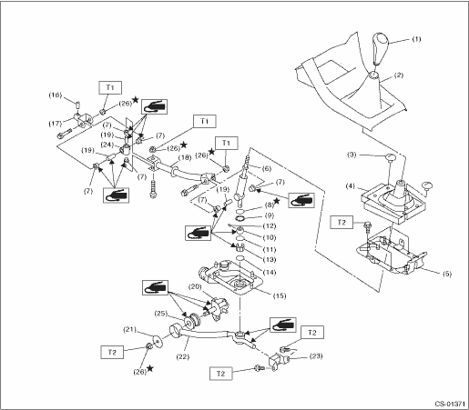
(1) | Gear shift knob | (11) | O-ring | (21) | Plate |
(2) | Console front cover ASSY | (12) | Spring pin | (22) | Stay |
(3) | Clamp | (13) | Bushing B | (23) | Cushion rubber |
(4) | Boot and insulator ASSY | (14) | O-ring | (24) | Boss |
(5) | Plate COMPL | (15) | Boot | (25) | Bushing |
(6) | Lever | (16) | Spring pin | (26) | Self-locking nut |
(7) | Bushing | (17) | Joint | ||
(8) | Lock wire | (18) | Rod | Tightening torque: N·m (kgf-m, ft-lb) | |
(9) | Snap ring | (19) | Spacer | T1: | 12 (1.2, 8.9) |
(10) | Bushing | (20) | Shift bracket | T2: | 18 (1.8, 13.3) |
 Specification
CONTROL SYSTEMS > General DescriptionSPECIFICATIONItemSpecificationsSwing torque of rod against leverN (kgf, lb)3.7 (0.38, 0.83) or less ...
 Preparation tool
CONTROL SYSTEMS > General DescriptionPREPARATION TOOL1. SPECIAL TOOLILLUSTRATIONTOOL NUMBERDESCRIPTIONREMARKS — SUBARU SELECT MONITOR 4Used for setting of each function and troubleshooting for el ...
Other materials:
Removal
CONTINUOUSLY VARIABLE TRANSMISSION(TR580) > Parking PawlREMOVAL1. Remove the transmission assembly from the vehicle. Automatic Transmission Assembly > REMOVAL">2. Shift the range select lever to “N” range.3. Remove the extension case. Extension Case > REMOVAL"> ...
Dtc c1241 rear left abs sensor circuit
VEHICLE DYNAMICS CONTROL (VDC) (DIAGNOSTICS) > Diagnostic Procedure with Diagnostic Trouble Code (DTC)DTC C1241 REAR LEFT ABS SENSOR CIRCUITDTC detecting condition:• Defective ABS wheel speed sensor (broken wire, input voltage too high)• Defective harness connectorTrouble symptom:&bul ...
Vehicle Dynamics Control OFF indicator light
The
light illuminates when the Vehicle
Dynamics Control OFF switch is pressed
to deactivate the Vehicle Dynamics Control
system.
The Vehicle Dynamics Control system is
probably malfunctioning under any of the
following conditions. Have your vehicle
checked at a SUBARU dealer immediately ...
