Subaru Crosstrek Service Manual: Communication for initializing impossible
LAN SYSTEM (DIAGNOSTICS) > Subaru Select Monitor
COMMUNICATION FOR INITIALIZING IMPOSSIBLE
DIAGNOSIS:
Subaru Select Monitor communication line is open or shorted.
TROUBLE SYMPTOM:
Not communicable with Subaru Select Monitor.
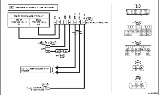
WIRING DIAGRAM:
CAN communication system CAN Communication System > WIRING DIAGRAM">
| STEP | CHECK | YES | NO |
1.CHECK SUBARU SELECT MONITOR.
1) Connect the Subaru Select Monitor to another vehicle.
2) Check communication condition between Subaru Select Monitor and vehicle.
Is communication performed normally?
Subaru Select Monitor > COMMUNICATION FOR INITIALIZING IMPOSSIBLE">Go to Step 2.
Subaru Select Monitor unit or diagnosis cable is faulty. Or check the fuse on the vehicle side.
2.CHECK COMMUNICATION FOR INITIALIZING ERROR.
Perform the communication for initializing with each module by connecting the Subaru Select Monitor. (For systems whose module can communicate with diagnostic devices)
Is the communication possible with all modules?
Subaru Select Monitor > COMMUNICATION FOR INITIALIZING IMPOSSIBLE">Go to Step 3.
Perform the inspection using the check sheet of communication for initializing. Subaru Select Monitor > COMMUNICATION FOR INITIALIZING IMPOSSIBLE">
3.CHECK K-LINE.
1) Establish the communication between Select Monitor and K-Line communication module.
2) Using a tester, check continuity between the modules that did not communicate with Select Monitor.
Connector & terminal
(B40) No. 7 — (B450) No. 2 (electric power steering):
Is there continuity?
Subaru Select Monitor > COMMUNICATION FOR INITIALIZING IMPOSSIBLE">Go to Step 4.
Repair or replace the open circuit.
4.CHECK K-LINE.
Using a tester, check continuity between K-line and chassis ground.
Connector & terminal
(B40) No. 7 — Chassis ground:
Is there continuity?
Repair or replace the short circuit portion.
Subaru Select Monitor > COMMUNICATION FOR INITIALIZING IMPOSSIBLE">Go to Step 5.
5.CHECK K-LINE.
Using a tester, check voltage between K-line and chassis ground.
Connector & terminal
(B40) No. 7 (+) — Chassis ground (−):
Is the voltage 5 V or more with IG ON?
Repair or replace the short circuit portion.
Subaru Select Monitor > COMMUNICATION FOR INITIALIZING IMPOSSIBLE">Go to Step 6.
6.CHECK K-LINE.
Use a tester to check for continuity in the ground circuit.
Connector & terminal
(B40) No. 4 — Chassis ground:
(B40) No. 5 — Chassis ground:
Is there continuity?
Subaru Select Monitor > COMMUNICATION FOR INITIALIZING IMPOSSIBLE">Go to Step 8.
Subaru Select Monitor > COMMUNICATION FOR INITIALIZING IMPOSSIBLE">Go to Step 7.
7.CHECK K-LINE.
1) Disconnect the ECM connector.
2) Use a tester to check for continuity in the ground circuit.
Connector & terminal
(B40) No. 4 — (B136) No. 1:
(B40) No. 5 — (B137) No. 4:
Is there continuity?
Check ECM ground.
Repair or replace the open circuit.
8.CHECK K-LINE.
1) Turn the ignition switch to ON.
2) Using a tester, check the power supply of data link connector.
Connector & terminal
(B40) No. 8 (+) — Chassis ground (−):
(B40) No. 16 (+) — Chassis ground (−):
Is the voltage 10 V or more?
K-Line is normal. Check the power supply circuit of each module.
Check the power supply circuits to the data link connector.
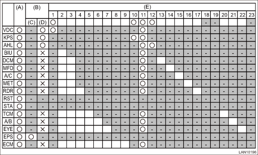
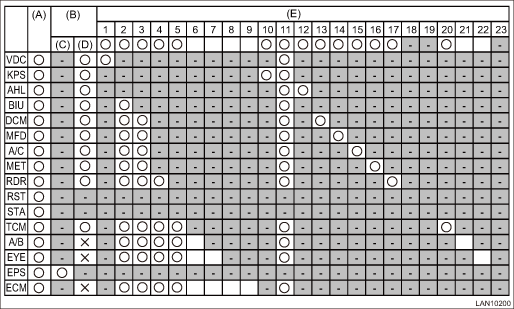
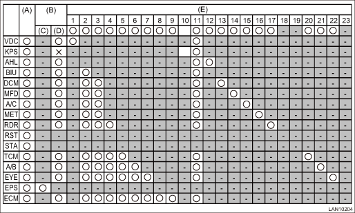
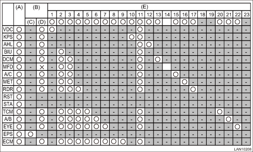
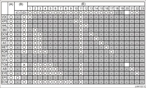
1. CHECK USING THE CHECK SHEET OF COMMUNICATION FOR INITIALIZING
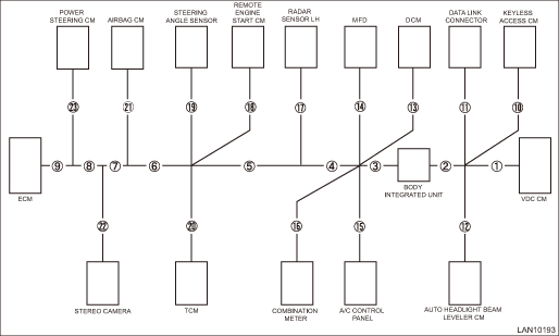
• Network diagram
• Check sheet of communication for initializing
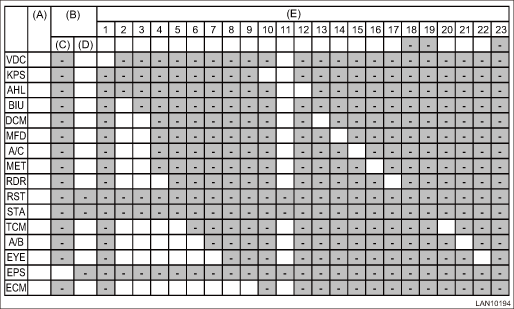
(A) | Installation check | VDC: VDC CM | RST: Remote engine starter CM |
(B) | Communication initialization | KPS: Keyless access CM | STA: Steering angle sensor |
(C) | K-Line | AHL: Auto headlight beam leveler CM | TCM: Transmission CM |
(D) | CAN | BIU: Body integrated unit | A/B: Airbag CM |
(E) | Wiring location | MFD: High grade MFD | EPS: Power steering CM |
A/C: A/C control panel | EYE: Stereo camera | ||
MET: Combination meter | ECM: Engine CM | ||
DCM: Data communication module | RDR: Radar sensor |
1. Module installation check
(1) Write “-” marks in the field for installation check if the vehicle to be inspected does not have relevant module.
(2) Write “-” marks in all blank fields on the same row that the “-” mark has filled in.
NOTE:
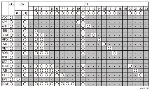
Example of writing Subaru Select Monitor > COMMUNICATION FOR INITIALIZING IMPOSSIBLE">
2. Subaru Select Monitor communication initialization check
(1) Write “ ” marks in the field for communication initialization if the module succeeded in the communication for initializing with Select Monitor.
If the communication with all modules is not possible, go to 3).
(2) Write “” marks in all blank fields on the same row that the “” mark has filled in.
(3) When at least one field in a column of wiring location is filled with the “” mark, then the wiring for that location is normal. Write “” marks in all blank fields on the same column that the “” mark has filled in under the circled number.
(4) Check the open circuit of the modules which have no “” mark in their columns of the wiring location in ascending order. (only for installed modules)
(5) If the communication is not possible after checking all harnesses, check the module power supply line.
(6) Replace the module if the power supply line is normal.
NOTE:
• Example of writing Subaru Select Monitor > COMMUNICATION FOR INITIALIZING IMPOSSIBLE">
• Inspection using the communication for initializing of Subaru Select Monitor cannot be used to diagnose the wiring location marked with “-”. Example of DTC data not received List of Diagnostic Trouble Code (DTC) > LIST"> should be used to identify the faulty portion.
3. Subaru Select Monitor communication initialization check (impossible to communicate with all modules)
NOTE:
If at least one module becomes possible to communicate, return to 2).
(1) Check for the short circuit to ground. CAN Communication Circuit Check > INSPECTION"> If it is normal, go to the next.
(2) Check for the short circuit to battery. CAN Communication Circuit Check > INSPECTION"> If it is normal, go to the next.
(3) Perform the inspection for the resistance of 52 ? or less (short between wires). CAN Communication Circuit Check > INSPECTION"> If it is normal, go to the next.
(4) Check for the open circuit of network diagram No. 10 (data link connector).
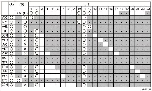
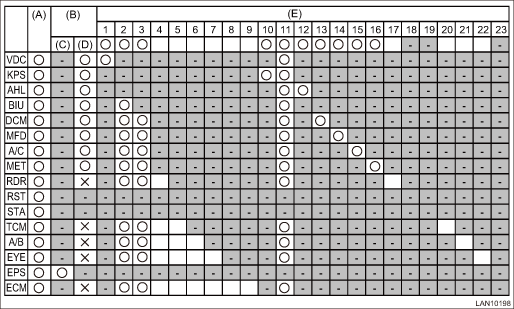
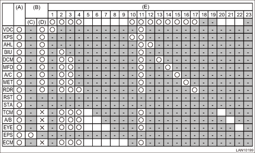
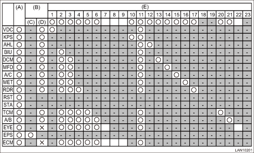
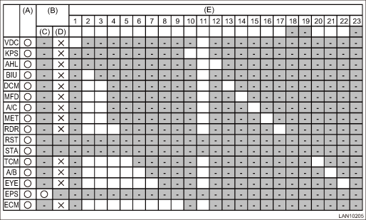
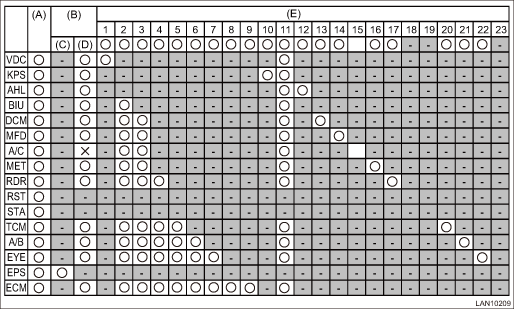
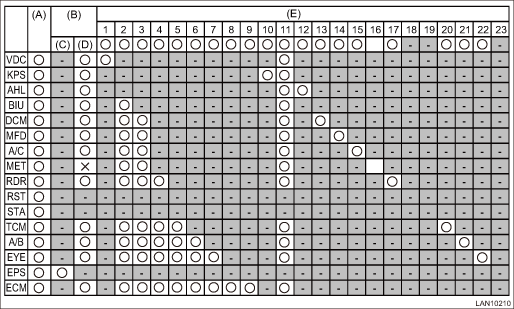
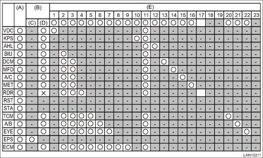
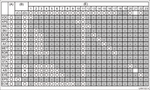
2. EXAMPLE OF WRITING FOR THE CHECK SHEET OF COMMUNICATION FOR INITIALIZING
When  is open
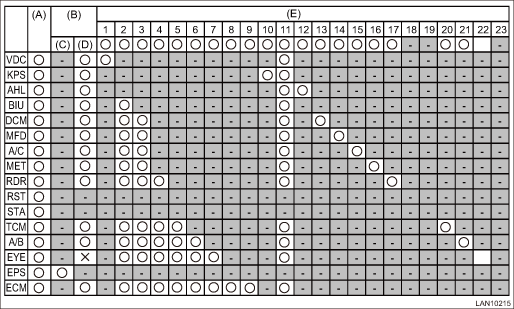
When  is open
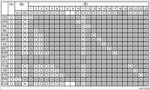
When  is open
When  is open
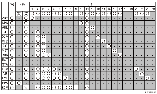
When  is open
When  is open
When  is open
When  is open
NOTE:
It is the same as in the case of No. 9 open circuit. However, determination is possible through the difference in the data no-receive detection condition of each module. List of Diagnostic Trouble Code (DTC) > LIST">
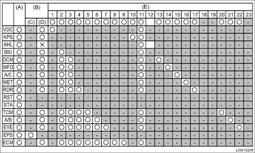
When  is open
NOTE:
It is the same as in the case of No. 8 open circuit. However, determination is possible through the difference in the data no-receive detection condition of each module. List of Diagnostic Trouble Code (DTC) > LIST">
When  is open
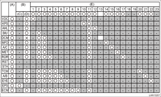
When  is open
NOTE:
Perform inspection by referring to 3) communication initialization check (impossible to communicate with all modules). (There may be a malfunction other than No. 11 open circuit)
When  is open
When  is open
When  is open
When  is open
When  is open
When  is open
When  is open
NOTE:
It is the same as in the case of No. 19, 23 open circuit. However, determination is possible through the difference in the data no-receive detection condition of each module. List of Diagnostic Trouble Code (DTC) > LIST">

When  is open
NOTE:
It is the same as in the case of No. 18, 23 open circuit. However, determination is possible through the difference in the data no-receive detection condition of each module. List of Diagnostic Trouble Code (DTC) > LIST">
When  is open
When  is open
When  is open
When  is open
NOTE:
It is the same as in the case of No. 18, 19 open circuit. However, determination is possible through the difference in the data no-receive detection condition of each module. List of Diagnostic Trouble Code (DTC) > LIST">
 Operation
LAN SYSTEM (DIAGNOSTICS) > Subaru Select MonitorOPERATIONFor detailed operation procedures, refer to “Application help”. ...
 Basic diagnostic procedure Procedure
LAN SYSTEM (DIAGNOSTICS) > Basic Diagnostic ProcedurePROCEDURECAUTION:• Subaru Select Monitor is required for reading DTC, performing diagnosis, reading current data, customizing and active t ...
Other materials:
Dtc u0131 lost communication with power steering control module
LAN SYSTEM (DIAGNOSTICS) > Diagnostic Procedure with Diagnostic Trouble Code (DTC)DTC U0131 LOST COMMUNICATION WITH POWER STEERING CONTROL MODULEDTC DETECTING CONDITION:No data is received from power steering CM.TROUBLE SYMPTOM:Cooperation control with power steering CM does not operate properly. ...
Event record data Operation
AIRBAG SYSTEM (DIAGNOSTICS) > Event Record DataOPERATION1. On «Start» display, select «Diagnosis».2. On «Vehicle selection» display, input the target vehicle information and select «Confirmed».3. On «Main Menu» display, select «Each System».4. On «Select System» display, select «Ai ...
Adjustment
CONTROL SYSTEMS > Select CableADJUSTMENT1. Shift the select lever to “N” range.2. Lift up the vehicle.3. Remove the center exhaust pipe. Center Exhaust Pipe > REMOVAL">4. Remove the center exhaust cover.5. Loosen the adjusting nuts on both sides.(A)Adjusting nut A(B)Adjust ...
