Subaru Crosstrek Service Manual: Check power supply and ground line of engine control module (ecm)
ENGINE (DIAGNOSTICS)(H4DO) > Diagnostics for Engine Starting Failure
CHECK POWER SUPPLY AND GROUND LINE OF ENGINE CONTROL MODULE (ECM)
CAUTION:
After servicing or replacing faulty parts, perform Clear Memory Mode Clear Memory Mode > OPERATION"> , and Inspection Mode Inspection Mode > PROCEDURE">.
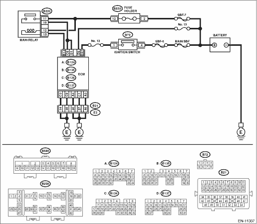
WIRING DIAGRAM:
Engine electrical system Engine Electrical System">
| STEP | CHECK | YES | NO |
1.CHECK MAIN RELAY.
1) Turn the ignition switch to OFF.
2) Remove the main relay.
3) Connect the battery to main relay terminals No. 12 and No. 13.
4) Measure the resistance between main relay terminals.
Terminals
No. 10 — No. 11:
Is the resistance less than 1 ??
Diagnostics for Engine Starting Failure > CHECK POWER SUPPLY AND GROUND LINE OF ENGINE CONTROL MODULE (ECM)">Go to Step 2.
Replace the main relay. Main Relay">
2.CHECK GROUND CIRCUIT FOR ECM.
1) Disconnect the connector from ECM.
2) Measure the resistance of harness between ECM connector and chassis ground.
Connector & terminal
(B134) No. 3 — Chassis ground:
(B134) No. 4 — Chassis ground:
(B136) No. 1 — Chassis ground:
(B136) No. 2 — Chassis ground:
(B136) No. 3 — Chassis ground:
Is the resistance less than 5 ??
Diagnostics for Engine Starting Failure > CHECK POWER SUPPLY AND GROUND LINE OF ENGINE CONTROL MODULE (ECM)">Go to Step 3.
Repair the harness and connector.
NOTE:
In this case, repair the following item:
• Open circuit of harness between ECM connector and engine ground terminal
• Poor contact of coupling connector
3.CHECK INPUT VOLTAGE OF ECM.
1) Turn the ignition switch to ON.
2) Measure the voltage between ECM connector and chassis ground.
Connector & terminal
(B137) No. 2 (+) — Chassis ground (−):
(B137) No. 27 (+) — Chassis ground (−):
Is the voltage 10 V or more?
Diagnostics for Engine Starting Failure > CHECK POWER SUPPLY AND GROUND LINE OF ENGINE CONTROL MODULE (ECM)">Go to Step 4.
Repair the open or ground short circuit of harness of power supply circuit.
4.CHECK INPUT VOLTAGE OF MAIN RELAY.
Measure the voltage between main relay connector and chassis ground.
Connector & terminal
(B220) No. 11 (+) — Chassis ground (−):
(B220) No. 12 (+) — Chassis ground (−):
Is the voltage 10 V or more?
Diagnostics for Engine Starting Failure > CHECK POWER SUPPLY AND GROUND LINE OF ENGINE CONTROL MODULE (ECM)">Go to Step 5.
Repair the open or ground short circuit of harness of power supply circuit.
5.CHECK INPUT VOLTAGE OF ECM.
1) Turn the ignition switch to OFF.
2) Install the main relay.
3) Turn the ignition switch to ON.
4) Measure the voltage between ECM connector and chassis ground.
Connector & terminal
(B135) No. 13 (+) — Chassis ground (−):
Is the voltage 10 V or more?
Diagnostics for Engine Starting Failure > CHECK POWER SUPPLY AND GROUND LINE OF ENGINE CONTROL MODULE (ECM)">Go to Step 6.
Repair the open circuit of harness between ECM connector and main relay connector.
6.CHECK INPUT VOLTAGE OF ECM.
1) Turn the ignition switch to OFF.
2) Connect the connector to ECM.
3) Turn the ignition switch to ON.
4) Measure the voltage between ECM connector and chassis ground.
Connector & terminal
(B136) No. 6 (+) — Chassis ground (−):
(B137) No. 1 (+) — Chassis ground (−):
Is the voltage 10 V or more?
Check ignition control system. Diagnostics for Engine Starting Failure > IGNITION CONTROL SYSTEM">
Repair the harness and connector.
NOTE:
In this case, repair the following item:
• Open circuit in harness between ECM connector and main relay connector
• Poor contact of main relay connector
• Poor contact of ECM connector

 Starter motor circuit
ENGINE (DIAGNOSTICS)(H4DO) > Diagnostics for Engine Starting FailureSTARTER MOTOR CIRCUIT1. MODEL WITHOUT PUSH BUTTON STARTCAUTION:After servicing or replacing faulty parts, perform Clear Memory Mo ...
Other materials:
Cruise control system
Note
CRUISE CONTROL SYSTEM > Cruise Control SystemNOTEFor operation procedures of each component of the cruise control system, refer to the respective section.• Control module: Control Unit">NOTE:System control of the cruise control is performed by each module. For procedure, refe ...
Conditions in which front passenger's
SRS frontal airbag is activated
The front passenger's SRS frontal airbag
will be activated for deployment upon
impact when any of the following conditions
are met regarding the front passenger's
seat.
When the seat is occupied by an adult.
When certain items (e.g. jug of water)
are placed on the seat.
If the passeng ...
Assembly
MANUAL TRANSMISSION AND DIFFERENTIAL(5MT) > Center DifferentialASSEMBLYInstall the ball bearings.CAUTION:Do not apply a load in excess of 10 kN (1 ton, 1.1 US ton, 1.0 Imp ton).NOTE:Use a new ball bearing.(A)Ball bearing ...
