Subaru Crosstrek Service Manual: Assembly
FRONT SUSPENSION > Front Arm
ASSEMBLY
1. BUSHING FRONT - FRONT ARM
1. Before assembly, inspect the following items and replace any faulty part with a new one.
• Check the front arm assembly for damage or cracks, and replace if defective.
• Visually check the bushing for abnormal cracks, fatigue or damage.
• Visually check the dust cover on the ball joint assembly for damage.
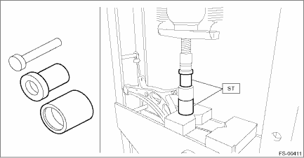
2. Align the alignment mark on the front arm assembly to the split portion of the bushing intermediate plate of the busing front - front arm.
3. Using the ST and a press, assemble the busing front - front arm.
PREPARATION TOOL:
ST: INSTALLER & REMOVER SET (927680000)
2. BUSHING REAR - FRONT ARM
1. Before installation, inspect the following items and replace any faulty part with a new one.
• Check the front arm assembly for damage or cracks, and replace if defective.
• Visually check the bushing for abnormal cracks, fatigue or damage.
• Visually check the dust cover on the ball joint assembly for damage.
2. Align a line extending from the center of recess portion with the ball joint after placing the protrusion (A) of recess portion to the ball joint side of the front arm assembly.
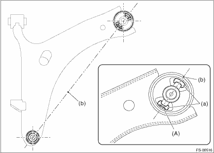
(a) | Recess section | (b) | Center line of recess section |
3. Using the ST and a press, install the busing rear - front arm.
CAUTION:
Align the upper face of front arm assembly and the end of bushing during installation.
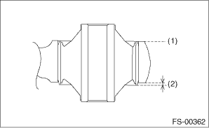
(1) | Aligned |
(2) | Not aligned |
PREPARATION TOOL:
ST1: REMOVER (20299AG000)
ST2: BASE (20299AG010)
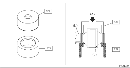
(a) | Press | (b) | Front arm ASSY | (c) | Bushing rear - front arm |
 Front arm
...
 Removal
FRONT SUSPENSION > Front ArmREMOVAL1. Lift up the vehicle, and then remove the front wheels.2. Remove the under cover - front. Front Under Cover > REMOVAL">3. Remove the front arm assem ...
Other materials:
Towing
If towing is necessary, it is best done by
your SUBARU dealer or a commercial
towing service. Observe the following
procedures for safety.
WARNING
Never tow AWD models with the
front wheels raised off the ground
while the rear wheels are on the
ground, or with the rear wheels
raised off t ...
Inspection
STARTING/CHARGING SYSTEMS(H4DO) > Battery Current & Temperature SensorINSPECTION1. BATTERY CURRENT SENSORCAUTION:Pay attention to polarity when checking the resistance in the battery current sensor.Check the resistance between the battery current sensor terminals.Terminal No.Standard1 (+) and ...
Dtc b28b5 +b circuit open
EyeSight (DIAGNOSTICS) > Diagnostic Procedure with Diagnostic Trouble Code (DTC)DTC B28B5 +B CIRCUIT OPENDetected when there is an open circuit in power supply line.NOTE:Refer to DTC B2814 for diagnostic procedure. Diagnostic Procedure with Diagnostic Trouble Code (DTC) > DTC B2814 POWER SUPP ...
