Subaru Crosstrek Service Manual: Assembly
DRIVE SHAFT SYSTEM > Front Drive Shaft
ASSEMBLY
1. Roll up a thick piece of paper to a size where the shaft can pass through, and affix with tape to form a cylinder.
2. Attach a new O-ring on this cylinder.
CAUTION:
• Always use a new O-ring.
• Be careful that the O-ring does not become scratched and that there are no foreign objects attached to it.
• Make sure to install the O-ring so that it does not twist as much as possible.
• Do not stretch the O-ring to 30 mm (1.18 in) inner diameter or more.

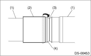
(1) | O-ring |
(2) | Cylinder made with thick paper, etc. |
3. Pass the cylinder material onto the shaft, and slide in the direction of the shaft axis.

(1) | Cylinder material |
(2) | O-ring |
(3) | Shaft |
4. Clean the shaft boot groove, and wipe off the grease.
5. Slide the cylinder material near the shaft boot groove, and move the O-ring from the cylinder material onto the shaft boot groove.
CAUTION:
• Attach the O-ring to the shaft boot groove center.
• Be careful that the O-ring does not become scratched and that there are no foreign objects attached to it.
• Make sure to install the O-ring so that it does not twist as much as possible.
• With the O-ring attached, do not wash with kerosene, gasoline, etc.
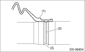
(1) | Shaft |
(2) | Cylinder material |
(3) | O-ring |
(4) | Boot groove |
6. Pass the small diameter boot band through the shaft.
7. Wrap vinyl tape around the splines of the shaft.
CAUTION:
To prevent damage to the boots, make sure to always wrap with vinyl tape for protection.
8. Install a new boot (PTJ).
CAUTION:
Make sure to fit securely on the boot groove of the shaft.
(1) | Boot (PTJ) |
(2) | O-ring |
(3) | Boot groove |
9. Match the alignment marks, and attach the trunnion onto the shaft.
10. Attach the snap ring to the shaft.
CAUTION:
Confirm that the snap ring is completely fitted in the shaft groove.
11. Fill 100 to 110 g (3.53 to 3.88 oz) of specified grease into the interior of the outer race (PTJ).
Grease:
NKG302
12. Apply a thin coat of specified grease to the roller kit and trunnion.
13. Match the alignment marks of the roller kit and trunnion, and attach the roller kit.
CAUTION:
Be careful with the roller kit position.
14. Match the alignment marks of the shaft and outer race (PTJ), and attach the outer race (PTJ).
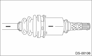
15. Install the snap ring in the groove of the outer race (PTJ).
CAUTION:
Pull the shaft lightly and make sure that the snap ring is completely fitted in the groove.
16. Apply an even coat of the specified grease 30 to 40 g (1.06 to 1.41 oz) to the entire inner surface of boot (PTJ).
17. Attach the boot (PTJ) taking care not to twist it.
CAUTION:
• Clean the large end of boot (PTJ) and the boot groove well, and remove the grease and other substances.
• When installing the boot (PTJ), position the outer race (PTJ) at center of the stroke.
18. Set the new boot band at the specified position.
19. Tighten the boot bands using ST, torque wrench and socket flex handle.
CAUTION:
The large boot band is to be tightened so that the omega shaped part is at the position indicated in the figure below.
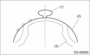
(1) | Omega shaped part |
(2) | Boot band |
(3) | Outer race (PTJ) |
Tightening torque:
Large boot band
178 N·m (18.2 kgf-m, 131.3 ft-lb)
Small boot band
145 N·m (14.8 kgf-m, 106.9 ft-lb)
| ST 28099AC000 | BOOT BAND PLIERS |
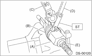
(A) | Large boot band |
(B) | Boot (PTJ) |
(C) | Torque wrench |
(D) | Socket flex handle |
(E) | Outer race (PTJ) |
20. Extend and retract the PTJ repeatedly so that grease is spread evenly.

 Removal
DRIVE SHAFT SYSTEM > Front Drive ShaftREMOVAL1. Lift up the vehicle, and then remove the front wheels.2. Remove the axle nut.CAUTION:Do not loosen the axle nut while the front axle is loaded. Doing ...
Other materials:
Preparation tool
HVAC SYSTEM (HEATER, VENTILATOR AND A/C) > General DescriptionPREPARATION TOOL1. SPECIAL TOOLILLUSTRATIONTOOL NUMBERDESCRIPTIONREMARKS — SUBARU SELECT MONITOR 4Used for setting of each function and troubleshooting for electrical system.NOTE:For detailed operation procedures of Subaru Select Mon ...
General diagnostic table Inspection
ENGINE (DIAGNOSTICS)(H4DO) > General Diagnostic TableINSPECTION1. ENGINENOTE:Malfunction of parts other than those listed is also possible. Engine Trouble in General">SymptomsFaulty parts1. Engine stalls during idling.1) Manifold absolute pressure sensor2) Mass air flow and intake air te ...
Inspection
MECHANICAL(H4DO) > Cam CarrierINSPECTION1. Visually check the cam carrier filter, and if clogging is found, replace with a new part.2. Check the camshaft journals for damage and wear. Replace the camshaft if faulty.3. Check the cam face condition of camshaft, and remove the minor faults by grindi ...
