Subaru Crosstrek Service Manual: Assembly
DIFFERENTIALS > Rear Differential (VA-type)
ASSEMBLY
NOTE:
• Assemble in the reverse order of disassembly.
• Check and adjust each part during assembly.
• Keep the shims and washers in order, so that they are not improperly installed.
• Thoroughly clean the surfaces on which the shims, washers and bearings are to be installed.
• Apply differential gear oil when installing the bearings and thrust washers.
• Be careful not to mix up the RH and LH bearing races.
• Replace the gasket, oil seal and O-ring with a new part.
• Be careful not to mix up the rear differential side oil seal RH and LH.
• Apply differential gear oil to the lips when installing the oil seal.
1. Adjusting preload for front and rear bearings
NOTE:
Adjust the bearing preload between front and rear bearings with preload adjusting spacer and washer. Pinion height adjusting washer is not affected by this adjustment. The adjustment must be carried out with oil seal removed.
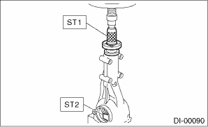
(1) Install the rear bearing race into the differential carrier using ST1 and ST2.
| ST1 398477701 | HANDLE |
| ST2 398477702 | DRIFT |
(2) Install the front bearing race to the differential carrier using ST1 and ST2.
NOTE:
Use a new front bearing race.
| ST1 398477701 | HANDLE |
| ST2 498447110 | DRIFT |
(3) Insert the front bearing cone.
NOTE:
Use new front bearing cone.
(4) Measure and record the thickness of the pinion height adjusting washer.
NOTE:
• At this time, install a provisionally selected or previously used pinion height adjusting washer.
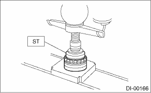
• If tooth contact (drive pinion and hypoid driven gear) is normal in the inspection before disassembling, verify that the washer is not deformed, and then reuse the used washer.
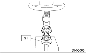
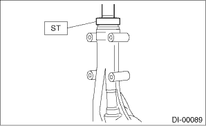
(5) Insert the ST (DUMMY SHAFT) into case with the pinion height adjusting washer and rear bearing cone fitted onto it.
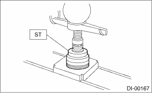
(6) Install the preload adjusting spacer, washer, front bearing cone, spacer, pilot bearing, companion flange, and self-locking nut.
NOTE:
Use a new pilot bearing.
| ST 498447150 | DUMMY SHAFT |
| Part No. 32285AA000 | Spacer |
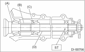
(A) | Pinion height adjusting washer |
(B) | Preload adjusting spacer |
(C) | Preload adjusting washer |
(D) | Spacer (SUBARU genuine parts) |
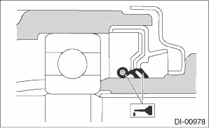
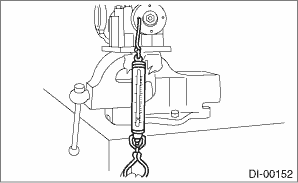
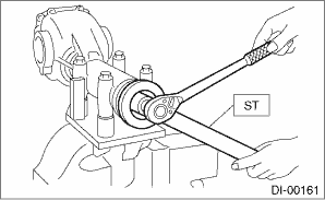
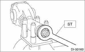
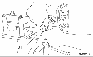
(7) Turn the ST by hand to slowly seat the bearing, and tighten the self-locking nut while measuring the initial load or initial torque with a spring scale or torque wrench. Select the preload adjusting washer and spacer so that the specified preload is obtained when nut is tightened to the specified torque.
NOTE:
• Use a new self-locking nut.
• Measure the preload in direction of tangent to the flange.
• Be careful not to give excessive preload.
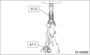
• When tightening the self-locking nut, lock ST1 with ST2 as shown in the figure.
| ST1 498447150 | DUMMY SHAFT |
| ST2 398507704 | BLOCK |
Tightening torque:
191 N·m (19.5 kgf-m, 140.9 ft-lb)
Initial load:
12.7 — 32.2 N (1.3 — 3.3 kgf, 2.9 — 7.2 lbf)
Initial torque:
0.48 — 1.22 N·m (0.05 — 0.12 kgf-m, 0.35 — 0.90 ft-lb)
Preload adjusting washer | |
Part No. | Thickness mm (in) |
38336AA000 | 1.500 (0.0591) |
38336AA120 | 1.513 (0.0596) |
38336AA010 | 1.525 (0.0600) |
38336AA130 | 1.538 (0.0606) |
38336AA020 | 1.550 (0.0610) |
38336AA140 | 1.563 (0.0615) |
38336AA030 | 1.575 (0.0620) |
38336AA150 | 1.588 (0.0625) |
38336AA040 | 1.600 (0.0630) |
38336AA160 | 1.613 (0.0635) |
38336AA050 | 1.625 (0.0640) |
38336AA170 | 1.638 (0.0645) |
38336AA060 | 1.650 (0.0650) |
38336AA180 | 1.663 (0.0655) |
38336AA070 | 1.675 (0.0659) |
38336AA190 | 1.688 (0.0665) |
38336AA080 | 1.700 (0.0669) |
38336AA200 | 1.713 (0.0674) |
38336AA090 | 1.725 (0.0679) |
38336AA210 | 1.738 (0.0684) |
38336AA100 | 1.750 (0.0689) |
38336AA220 | 1.763 (0.0694) |
38336AA110 | 1.775 (0.0699) |
Preload adjusting spacer | |
Part No. | Length mm (in) |
32288AA040 | 52.3 (2.059) |
32288AA050 | 52.5 (2.067) |
31454AA100 | 52.6 (2.071) |
32288AA060 | 52.7 (2.075) |
31454AA110 | 52.8 (2.079) |
32288AA070 | 52.9 (2.083) |
31454AA120 | 53.0 (2.087) |
32288AA080 | 53.1 (2.091) |
32288AA090 | 53.3 (2.098) |
2. Adjusting drive pinion height:
Adjust the drive pinion height with pinion height adjusting washer installed between the rear bearing cone and the back of pinion gear.
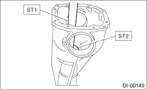
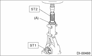
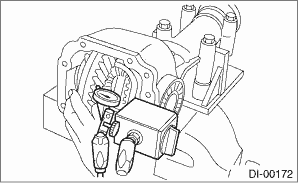
(1) Attach the ST2.
| ST1 498447150 | DUMMY SHAFT |
| ST2 498505501 | DIFFERENTIAL CARRIER GAUGE |
| Part No. 32285AA000 | Spacer |
(A) | Pinion height adjusting washer |
(B) | Spacer (SUBARU genuine parts) |
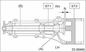
(2) Measure the clearance “N” between the end of ST2 and the end surface of ST1 by using a thickness gauge.
NOTE:
Make sure there is no clearance between the differential carrier and ST2.
| ST1 498447150 | DUMMY SHAFT |
| ST2 498505501 | DIFFERENTIAL CARRIER GAUGE |
(3) Calculate the thickness of pinion height adjusting washer to be inserted from the following formula, and replace the temporarily installed washer with a new washer of the calculated thickness.
NOTE:
Adjust it using the 1 — 3 washers.
T = To + N − 0.05 mm (0.0020 in)
T | Thickness of pinion height adjusting washer mm (in) |
|
To | Thickness of washer temporarily inserted mm (in) |
|
N | Clearance of thickness gauge mm (in) |
|
Memo:
| ||
(Example of calculation)
To = 0.15 mm (0.0059 in)
N = 0.1 mm (0.0039 in)
T = 0.15 + 0.1 − 0.05 = 0.2 mm (0.0079 in)
Result: Thickness = 0.2 mm (0.0079 in)
Therefore use part number 32295AA220.
Pinion height adjusting washer | |
Part No. | Thickness mm (in) |
32295AA200 | 0.150 (0.0059) |
32295AA210 | 0.175 (0.0069) |
32295AA220 | 0.200 (0.0079) |
32295AA230 | 0.225 (0.0089) |
32295AA240 | 0.250 (0.0098) |
32295AA250 | 0.275 (0.0108) |
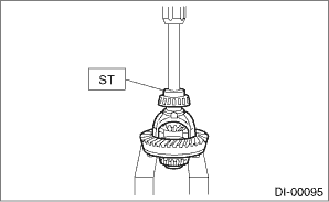
3. Install the selected pinion height adjusting washer on drive pinion, and press the rear bearing cone into position with ST.
| ST 498175500 | INSTALLER |
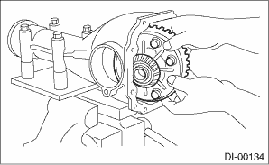
4. Insert the drive pinion into the differential carrier, and install the preselected preload adjusting spacer and washer.
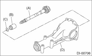
(A) | Drive pinion |
(B) | Preload adjusting spacer |
(C) | Preload adjusting washer |
(D) | Differential carrier |
5. Press-fit the front bearing cone into the carrier with ST1, ST2 and the spacer.
NOTE:
Use new front bearing cone.
| ST1 399780104 | WEIGHT |
| ST2 899580100 | INSTALLER |
| Part No. 32285AA000 | Spacer |
(A) | Spacer (SUBARU genuine parts) |
6. Insert the spacer, then press-fit the pilot bearing with ST1 and ST2.
NOTE:
Use a new pilot bearing.
| ST1 399780104 | WEIGHT |
| ST2 899580100 | INSTALLER |
7. Using the ST, install the oil seal.
NOTE:
• Use a new oil seal.
• Press-fit until the oil seal end comes 1 mm (0.04 in) inward from end of carrier.
• Apply differential gear oil to the oil seal lips.
| ST 498447120 | INSTALLER |
8. Press-fit the companion flange with ST1 and ST2.
NOTE:
Be careful not to damage the pilot bearing.
| ST1 899874100 | INSTALLER |
| ST2 399780104 | WEIGHT |
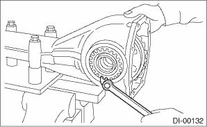
9. Attach the self-locking nut and use the ST to fix the companion flange in place, then tighten the self-locking nut.
NOTE:
• Use a new self-locking nut.
• Before installing the self-locking nut, apply the seal material to the threads of the drive pinion shaft and to the seating surface of the self-locking nut.
Seal material:
THREE BOND 1324 (Part No. 004403042) or equivalent
Tightening torque:
191 N·m (19.5 kgf-m, 140.9 ft-lb)
| ST 498427200 | FLANGE WRENCH |
10. Check the initial torque or initial load.
Initial load:
12.7 — 32.2 N (1.3 — 3.3 kgf, 2.9 — 7.2 lbf)
Initial torque:
0.48 — 1.22 N·m (0.05 — 0.12 kgf-m, 0.35 — 0.90 ft-lb)
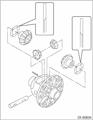
11. Assembling differential case
(1) Install the side gears and pinion mate gears, with their thrust washers and pinion mate shaft, into the differential case.
NOTE:
• Apply gear oil on both sides of the washer and on the side gear shaft before installing.
• Insert the pinion mate shaft into the differential case by aligning the pin holes.
• The side gear thrust washer inner surface has a chamfered side. Install the washer with the chamfered side facing toward the side gear.
(2) Measure the side gear backlash.
Side gear backlash:
0.05 — 0.15 mm (0.002 — 0.006 in)
(3) Adjust the side gear backlash by selecting side gear thrust washer.
Side gear thrust washer | |
Part No. | Thickness mm (in) |
803135011 | 0.925 — 0.950 (0.0364 — 0.0374) |
803135012 | 0.950 — 0.975 (0.0374 — 0.0384) |
803135013 | 0.975 — 1.000 (0.0384 — 0.0394) |
803135014 | 1.000 — 1.025 (0.0394 — 0.0404) |
803135015 | 1.025 — 1.050 (0.0404 — 0.0413) |
(4) Check the condition of rotation after applying oil to the gear tooth surfaces and washer surfaces.
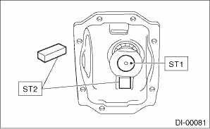
(5) Using the ST, drive the spring pin to the differential case.
NOTE:
Use new spring pin.
| ST 899904100 | STRAIGHT PIN REMOVER |
12. Install the hypoid driven gear to differential case.
NOTE:
• Before installing bolts, apply seal material to bolt threads.
Seal material:
THREE BOND 1324 (Part No. 004403042) or equivalent
• Tighten opposing bolts in order.
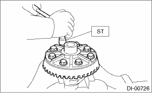
(1) Tighten the hypoid driven gear mounting bolts to the specified torque using the ST.
| ST 18270KA020 | SOCKET (E20) |
Tightening torque:
20 N·m (2.0 kgf-m, 14.8 ft-lb)
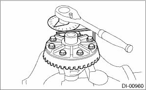
(2) While checking the tightening angle with the angle gauge, further tighten the hypoid driven gear mounting bolts.
Tightening angle:
35°±2°
13. Using the ST, press-fit the side bearing to the differential case.
| ST 498485400 | DRIFT |
14. Assemble the side retainer.
(1) Install the oil seal into side retainer RH and LH.
CAUTION:
Pay attention to the left and right of the oil seal.
NOTE:
• Use a new oil seal.
• Apply differential gear oil to the oil seal lip.
| ST 498447100 | INSTALLER |
(2) Install the bearing race into side retainer RH and LH.
CAUTION:
Make sure that bearing races and cones are properly assembled.
| ST 398477702 | DRIFT |
(3) Install the differential case assembly into differential carrier in the reverse order of disassembly.
NOTE:
Be careful not to hit the teeth of hypoid driven gear against the differential carrier.
(4) Temporally tighten the side retainers RH and LH in differential carrier to install.
15. Perform the backlash adjustment between the hypoid driven gear and drive pinion, and preload adjustment of differential side bearing.
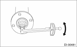
(1) Turn the drive pinion with ST for better fitting of differential side bearing.
| ST 498427200 | FLANGE WRENCH |
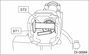
(2) Using the ST, tighten side retainer RH, and then tighten side retainer LH until there is no backlash.
| ST 18630AA010 | WRENCH COMPL RETAINER |
(3) Loosen the side retainer LH by approx. 1 and 1/2 teeth, and tighten the side retainer RH by approx. 2 teeth [amount that the side retainer LH is turned back (approx. 1 and 1/2 teeth) + approx. 1/2 teeth]. Difference between [amount that the side retainer LH is turned back (approx. 1 and 1/2 teeth)] and [amount that the side retainer RH is tightened (approx. 2 teeth)] gives preload.
(4) Temporarily tighten the lock plate.
NOTE:
Turn over the lock plate to shift the holder by 1/2 teeth.
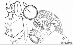
(5) Measure the hypoid driven gear-to-drive pinion backlash. Set the magnet base on differential carrier. Align the contact point of dial gauge with tooth face of hypoid driven gear, and move hypoid driven gear while holding drive pinion still. Read the value indicated on dial gauge.
NOTE:
If measured value of backlash is not within the specified range, repeat the procedures for pinion driven gear set backlash adjustment and the differential side bearing preload adjustment.
Backlash:
0.10 — 0.15 mm (0.004 — 0.006 in)
16. Put alignment marks on both the differential carrier and side retainer. Remove the side retainers one side at a time. After installing an O-ring and applying oil to the threaded portion, restore them to the original position.
NOTE:
Use new O-rings.
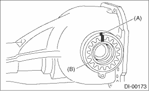
(A) | Alignment mark |
(B) | Side retainer |
17. Install the lock plate, and tighten the bolts to the specified torque.
Tightening torque:
25 N·m (2.5 kgf-m, 18.4 ft-lb)
18. Recheck the backlash between hypoid driven gear and drive pinion.
Backlash:
0.10 — 0.15 mm (0.004 — 0.006 in)
19. Checking and adjusting the tooth contact of hypoid driven gear
(1) Apply lead-free red dye evenly on the both sides of three to four teeth of the hypoid driven gear. Check the contact pattern after rotating the hypoid driven gear several revolutions back and forth until a definite contact pattern appears on the hypoid driven gear.
(2) When the contact pattern is not correct, readjust.
NOTE:
Be sure to wipe off the lead-free red dye completely after the adjustment is completed.
• Correct tooth contact
Check item: Tooth contact pattern is slightly shifted toward toe side under no-load rotation. (When driving, it moves towards the heel side.)
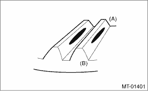
(A) | Toe side |
(B) | Heel side |
• Face contact
Check item: Backlash is t Electrical component location Location Component Dtc b1823 short in side airbag rh (to +b)
DIFFERENTIALS > Rear Differential (VA-type)ADJUSTMENT1. SIDE GEAR BACKLASHAdjust the side gear backlash. Rear Differential (VA-type) > ASSEMBLY">2. HYPOID DRIVEN GEAR BACKLASHAdjust hyp ...
 Adjustment
DIFFERENTIALS > Rear Differential (VA-type)DISASSEMBLYTo detect the real cause of trouble, inspect the following items before disassembling.• Tooth contact and backlash between hypoid driven ...
 Disassembly
Other materials:
LAN SYSTEM (DIAGNOSTICS) > Electrical Component LocationLOCATION(1)VDC CM(7)Combination meter(12)Data link connector(2)Power steering CM(8)A/C control panel(13)Transmission CM(3)Stereo camera(9)MFD(14)Airbag CM(4)Radar sensor LH(10)Data communication module (DCM)(15)Engine CM(5)Auto headlight bea ...
GLASS/WINDOWS/MIRRORS > General DescriptionCOMPONENT1. FRONT DOOR GLASS(1)Running channel - front door(5)Regulator & motor ASSY - frontTightening torque: N·m (kgf-m, ft-lb)(2)Glass ASSY - front door(6)Sash COMPL - partitionT1:2.2 (0.22, 1.6)(3)Weather strip outer - front door(7)Weather ...
AIRBAG SYSTEM (DIAGNOSTICS) > Diagnostic Chart with Trouble CodeDTC B1823 SHORT IN SIDE AIRBAG RH (TO +B)Diagnosis start condition:Ignition voltage is 10 V to 16 V.DTC detecting condition:• Side airbag harness (RH) is shorted to power supply.• Side airbag module (RH) is faulty.• ...
