Subaru Crosstrek Service Manual: Assembly
CONTROL SYSTEMS > MT Gear Shift Lever
ASSEMBLY
NOTE:
• Clean all the parts before assembly.
• Apply NIGTIGHT LYW No. 2 grease or equivalent to each part. General Description > COMPONENT">
1. Mount the bushing and cushion rubber to the stay.
(A) | Bushing |
(B) | Stay |
(C) | Cushion rubber |
2. Install the bushing and spacer to boss.
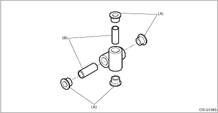
(A) | Bushing |
(B) | Spacer |
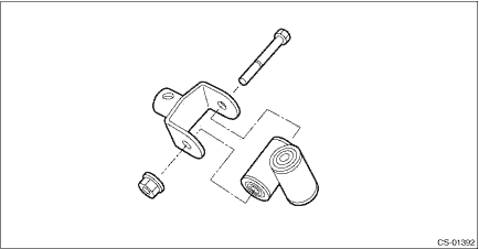
3. Install the boss to the joint.
NOTE:
Use a new self-locking nut.
Tightening torque:
12 N·m (1.2 kgf-m, 8.9 ft-lb)
4. Install the snap ring to gear shift lever and install the bushing.
NOTE:
Apply grease to the bushing.
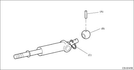
(A) | Spring pin |
(B) | Bushing |
(C) | Snap ring |
5. Apply grease to the bushing and O-ring, and then install to gear shift lever.
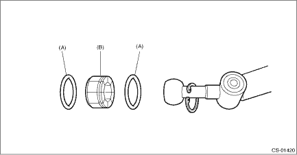
(A) | O-ring |
(B) | Bushing |
6. Apply sufficient grease into boss, and then install the gear shift lever to the stay.
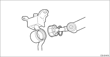
7. Install the snap ring.
(A) | Snap ring |
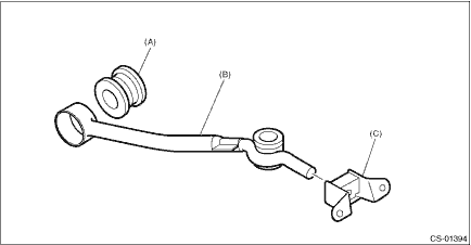
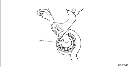
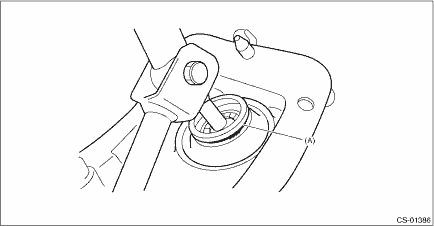
8. Insert the gear shift lever and rod into boot hole.
9. Install the rod.
NOTE:
Use a new self-locking nut.
Tightening torque:
12 N·m (1.2 kgf-m, 8.9 ft-lb)
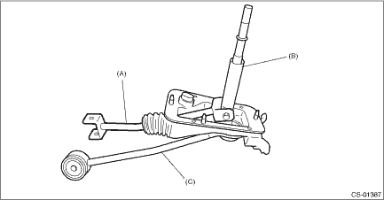
(A) | Rod |
(B) | Lever |
(C) | Stay |
10. Install the lock wire.
NOTE:
Use a new lock wire.
(A) | Lock wire |
NOTE:
• Install the lock wire to the stay groove.
• Bend the extra wire to the same direction of lock wire winding.
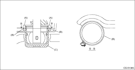
(A) | Inner boot |
(B) | Lock wire |
(C) | Stay |

 Removal
CONTROL SYSTEMS > MT Gear Shift LeverREMOVAL1. Disconnect the ground cable from battery. NOTE">NOTE:For model with battery sensor, disconnect the ground terminal from battery sensor.2. Rem ...
Other materials:
Dtc p062f internal control module eeprom error
CONTINUOUSLY VARIABLE TRANSMISSION (DIAGNOSTICS) > Diagnostic Procedure with Diagnostic Trouble Code (DTC)DTC P062F INTERNAL CONTROL MODULE EEPROM ERRORDTC DETECTING CONDITION:Detected when two consecutive driving cycles with fault occur.TROUBLE SYMPTOM:TCM EEPROM malfunctionSTEPCHECKYESNO1.CHECK ...
Basic diagnostic procedure Procedure
ENGINE (DIAGNOSTICS)(H4DO) > Basic Diagnostic ProcedurePROCEDURE1. ENGINESTEPCHECKYESNO1.CHECK ENGINE START FAILURE.1) Ask the customer when and how the trouble occurred using the interview check list. Check List for Interview > CHECK">2) Start the engine.Does the engine start? Basic ...
Caution
VEHICLE DYNAMICS CONTROL (VDC) (DIAGNOSTICS) > General DescriptionCAUTION1. SUPPLEMENTAL RESTRAINT SYSTEM “AIRBAG”Airbag system wiring harness is routed near the ABS wheel speed sensor and VDCCM&H/U.CAUTION:• Do not use electrical test equipment on wiring harness and connect ...
