Subaru Crosstrek Service Manual: 12
CRUISE CONTROL SYSTEM (DIAGNOSTICS) > Diagnostic Procedure with Cancel Code
12
Detected when brake pedal is depressed or malfunction related to stop light & brake switch occurs.
TROUBLE SYMPTOM:
• Cruise control cannot be set.
• Cruise control cannot be released.
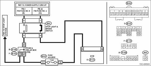
WIRING DIAGRAM:
Cruise control system Cruise Control System > WIRING DIAGRAM">
| STEP | CHECK | YES | NO |
1.CHECK STOP LIGHT & BRAKE SWITCH.
Check the stop light & brake switch. Stop Light & Brake Switch">
Is the stop light & brake switch and installation position OK?
Diagnostic Procedure with Cancel Code > 12">Go to Step 2.
Replace the stop light & brake switch. Or adjust the installation position.
2.CHECK STOP LIGHT & BRAKE SWITCH CIRCUIT.
1) Turn the ignition switch to OFF.
2) Disconnect the stop light & brake switch harness connector.
3) Turn the ignition switch to ON.
4) Measure the voltage between harness connector terminal and chassis ground.
Connector & terminal
(B65) No. 3 (+) — Chassis ground (−):
Is the voltage 10 V or more?
Diagnostic Procedure with Cancel Code > 12">Go to Step 3.
• Check fuse No. 8 (in fuse & relay box).
• Check for open or short in the harness between stop light & brake switch and fuse & relay box.
3.CHECK STOP LIGHT & BRAKE SWITCH CIRCUIT.
Measure the voltage between harness connector terminal and chassis ground.
Connector & terminal
(B65) No. 1 (+) — Chassis ground (−):
Is the voltage 10 V or more?
Diagnostic Procedure with Cancel Code > 12">Go to Step 4.
• Check fuse No. 4 (in fuse & relay box).
• Check for open or short in the harness between stop light & brake switch and fuse & relay box.
4.CHECK STOP LIGHT & BRAKE SWITCH CIRCUIT.
1) Turn the ignition switch to OFF.
2) Disconnect the harness connector of ECM.
3) Measure the resistance between ECM harness connector terminal and stop light & brake switch harness connector terminal.
Connector & terminal
(B137) No. 3 — (B65) No. 4:
(B137) No. 7 — (B65) No. 2:
Is the resistance less than 10 ??
Replace the ECM.
Engine Control Module (ECM)">
Repair the harness.
 49
49
CRUISE CONTROL SYSTEM (DIAGNOSTICS) > Diagnostic Procedure with Cancel Code49Automatic transmission malfunction is detected.Automatic transmission malfunction is detected during cruise driving or c ...
 13
13
CRUISE CONTROL SYSTEM (DIAGNOSTICS) > Diagnostic Procedure with Cancel Code13Detected when clutch pedal is depressed or malfunction related to clutch switch occurs.TROUBLE SYMPTOM:• Cruise co ...
Other materials:
Installation
WIPER AND WASHER SYSTEMS > Front Wiper ArmINSTALLATION1. MODELS WITHOUT EyeSight1. Install the arm assembly - windshield wiper.(1) Assemble the arm assembly - windshield wiper so that the blade assembly - windshield wiper is aligned to the ceramic print point mark of the windshield glass.(2) Tigh ...
Inspection
BRAKE > Brake PedalINSPECTION1. Move the pad - brake pedal in a horizontal direction with a force of approx. 10 N (1 kgf, 2 lbf), and check that the pedal deflection is in the range of specifications.CAUTION:If excessive deflection is noted, replace with a new bushing.Deflection of brake pedal:We ...
Dtc b14ea intake door actuator circuit short-circuit
HVAC SYSTEM (AUTO A/C) (DIAGNOSTICS) > Diagnostic Procedure with Diagnostic Trouble Code (DTC)DTC B14EA INTAKE DOOR ACTUATOR CIRCUIT SHORT-CIRCUITDTC detecting condition:Intake door actuator potentiometer circuit is shorted.Trouble symptom:FRESH/RECIRC does not operate.Wiring diagram:Air conditio ...
